


Philips Semiconductors Product specification
PTN3501Maintenance and control device
2001 Jan 17
9
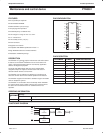
Read operations
PTN3501 read operations are initiated in an identical manner to
write operations with the exception that the memory slave address’
R/W
bit is set to a one. There are three types of read operations;
current address, random and sequential.
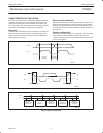
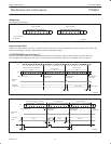
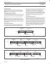
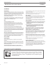
Current Address Read (see Figure 16)
The PTN3501 contains an internal address counter that increments
after each read or write access, as a result if the last word accessed
was at address n then the address counter contains the address
n+1.
When the PTN3501 receives its memory slave address with the
R/W
bit set to one it issues an acknowledge and uses the next eight
clocks to transmit the data contained at the address stored in the
address counter. The master ceases the transmission by issuing the
stop condition after the eighth bit. There is no ninth clock cycle for
the acknowledge.
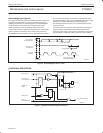
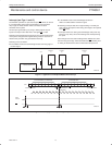
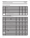
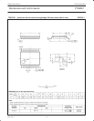
Random Read (see Figure 17)
The PTN3501’s random read mode allows the address to be read
from to be specified by the master. This is done by performing a
dummy write to set the address counter to the location to be read.
The master must perform a byte write to the address location to be
read, but instead of transmitting the data after receiving the
acknowledge from the PTN3501 the master reissues the start
condition and memory slave address with the R/W
bit set to one.
The PTN3501 will then transmit an acknowledge and use the next
eight clock cycles to transmit the data contained in the addressed
location. The master ceases the transmission by issuing the stop
condition after the eighth bit, omitting the ninth clock cycle
acknowledge.
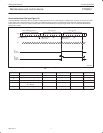
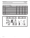
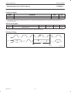
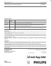
Sequential Read (see Figure 18)
The PTN3501 sequential read is an extension of either the current
address read or random read. If the master doesn’t issue a stop
condition after it has received the eighth data bit, but instead issues
an acknowledge, the PTN3501 will increment the address counter
and use the next eight cycles to transmit the data from that location.
The master can continue this process to read the contents of the
entire memory. Upon reaching address 255 the counter will return to
address 0 and continue transmitting data until a stop condition is
received. The master ceases the transmission by issuing the stop
condition after the eighth bit, omitting the ninth clock cycle
acknowledge.
S
P
SW00653
SLAVE ADDRESS
(MEMORY)
DATA FROM MEMORY
SDA
START
CONDITION
1A5A4A3A2A1A0 1 A
R/W
ACKNOWLEDGE
FROM SLAVE
STOP
CONDITION
Figure 16. Current Address Read
S
P
SDA
SW00654
SLAVE ADDRESS
(MEMORY)
WORD
ADDRESS
1 A5A4A3A2A1A0
A
A
0
START
CONDITION
R/W
ACKNOWLEDGE
FROM SLAVE
ACKNOWLEDGE
FROM SLAVE
A
ACKNOWLEDGE
FROM SLAVE
DATA FROM MEMORY
STOP
CONDITION
S
START
CONDITION
1A5A4A3A2A1A0
1
R/W
SLAVE ADDRESS
(MEMORY)
Figure 17. Random Read
S
P
SDA
SW00655
SLAVE ADDRESS
(MEMORY)
DATA
FROM MEMORY
DATA
FROM MEMORY
1 A5A4A3A2A1A0
A
A
1
START
CONDITION
R/W
ACKNOWLEDGE
FROM SLAVE
ACKNOWLEDGE
FROM MASTER
DATA n
A
ACKNOWLEDGE
FROM MASTER
DATA N+X
STOP
CONDITION
DATA n+1
DATA
FROM MEMORY
Figure 18. Sequential Read