


Philips Semiconductors Product specification
PTN3501Maintenance and control device
2001 Jan 17
6
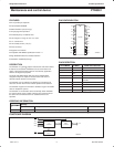
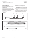
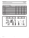
Interrupt (see Figs 11 and 12)
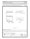
The PTN3501 provides an open drain output (INT) which can be fed
to a corresponding input of the microcontroller. This gives these
chips a type of master function which can initiate an action
elsewhere in the system.
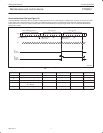
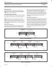
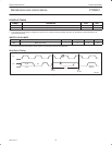
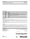
An interrupt is generated by any rising or falling edge of the port
inputs in the input mode. After time t
iv
the signal INT is valid.
Resetting and reactivating the interrupt circuit is achieved when data
on the port is changed to the original setting or data is read from or
written to the port which has generated the interrupt.
Resetting occurs as follows:
• In the READ mode at the acknowledge bit after the rising edge of
the SCL signal
• In the WRITE mode at the acknowledge bit after the
HIGH–to–LOW transition of the SCL signal
• Returning of the port data to its original setting. A second port
state change will require an SCL rising clock edge to be captured
as an INT
event.
• Interrupts which occur during the acknowledge clock pulse may
be lost (or very short) due to the resetting of the interrupt during
this pulse.
Each change of the I/Os after resetting will be detected and, after
the next rising clock edge, will be transmitted as INT. Reading from
or writing to another device does not affect the interrupt circuit.
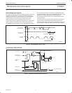
SW00790
PTN3501
(1)
INT
PTN3501
(2)
INT
PTN3501
(16)
INT
MICROCONTROLLER
INT
V
DD
Figure 11. Application of multiple PTN3501s with interrupt
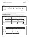
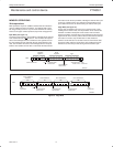
S 0 A5 A4 A3 A2 A1 A0 1 A 1 1SDA
SCL
12345678
t
ir
SW00791
ACKNOWLEDGE
FROM SLAVE
R/WSTART CONDITION STOP CONDITION
SLAVE ADDRESS (I/O EXPANDER)
DATA FROM PORT
DATA
INTO P5
INT
P
P5
t
iv
Figure 12. Interrupt generated by a change of input to I/O P5