


Philips Semiconductors Product specification
PTN3501Maintenance and control device
2001 Jan 17
3
CHARACTERISTICS OF THE I
2
C-BUS
The I
2
C-bus is for 2-way, 2-line communication between different ICs
or modules. The two lines are a serial data line (SDA) and a serial
clock line (SCL). Both lines must be connected to a positive supply
via a pull-up resistor when connected to the output stages of a device.
Data transfer may be initiated only when the bus is not busy.
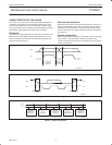
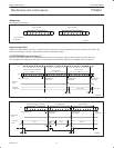
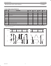
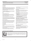
Bit transfer
One data bit is transferred during each clock phase. The data on the
SDA line must remain stable during the HIGH period of the clock
pulse as changes in the data line at this time will be interpreted as
control signals (See Figure 3).
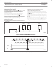
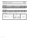
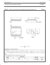
Start and stop conditions
Both data and clock lines remain HIGH when the bus is not busy. A
HIGH-to-LOW transition of the data line, while the clock is HIGH is
defined as the start condition (S). A LOW-to-HIGH transition of the
data line while the clock is HIGH is defined as the stop condition (P)
(see Figure 4).
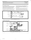
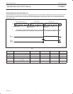
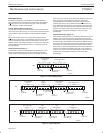
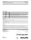
System configuration
A device generating a message is a “transmitter”, a device receiving
is the “receiver”. The device that controls the message is the
“master” and the devices which are controlled by the master are the
“slaves” (see Figure 5).
SDA
SCL
SW00542
DATA LINE
STABLE;
DATA VALID
CHANGE
OF DATA
ALLOWED
Figure 3. Bit transfer
SDA
SCL
P
SDA
SCL
S
SW00543
START CONDITION STOP CONDITION
Figure 4. Definition of start and stop conditions
SDA
SCL
SW00544
MASTER
TRANSMITTER/
RECEIVER
SLAVE
RECEIVER
SLAVE
TRANSMITTER/
RECEIVER
MASTER
TRANSMITTER
MASTER
TRANSMITTER/
RECEIVER
Figure 5. System configuration