


1998 Feb 16 20
Philips Semiconductors Product specification
CMOS digital decoding IC with RAM for
Compact Disc
SAA7345
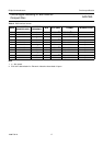
CHANNEL STATUS
The channel status bit is the same for left and right words. Therefore a block of 384 words contains 192 channel status
bits. The category code is always CD. The bit assignment is shown in Table 8.
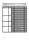
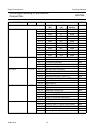
Table 8 EBU channel status
WORD BITS FUNCTION
Control 0 to 3 copy of CRC checked Q-channel control bits 0 to 3;
bit 2 is logic 1 when copy permitted;
bit 3 is logic 1 when recording has pre-emphasis
Reserved mode 4 to 7 always zero
Category code 8 to 15 CD: bit 8 = logic 1; all other bits = logic 0
Clock accuracy 28 to 29 set by EBU control register:
00 = Level II
01 = Level III
Remaining 16 to 27 and 30 to 191 always zero
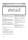
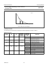
KILL circuit
The KILL circuit detects digital silence by testing for an
all-zero or all-ones data word in the left or right channel
before the digital filter. The output is switched active LOW
when silence has been detected for at least 200 ms. Two
modes are available, selected by the versatile pins register
(address 1100):
1-
PIN KILL MODE
Active LOW signal on KILL pin when digital silence has
been detected on both LEFT and RIGHT channels for
200 ms.
2-
PIN KILL MODE
Independent digital silence detection for left and right
channels. The KILL pin is active LOW when digital silence
has been detected in the LEFT channel for 200 ms, and V3
is active LOW when digital silence has been detected in
the RIGHT channel for 200 ms.
When MUTE is active then the KILL output is forced LOW.
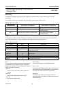
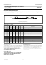
Spindle motor control
The spindle motor speed is controlled by a fully integrated
digital servo. Address information from the internal
±8 frame FIFO and disc speed information are used to
calculate the motor control output signals.
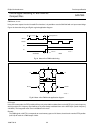
Several output modes are supported:
1. Pulse Density, 2-line (true complement output), 1 MHz
sample frequency.
2. PWM output, 2-line, 22.05 kHz modulation frequency.
3. PWM-output, 4-line, 22.05 kHz modulation frequency.
4. CDV motor mode.
The modes are selected via the motor output configuration
register (address 0110).
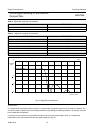
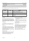
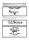
P
ULSE DENSITY MODE
In the Pulse Density mode the motor output pin MOTO1 is
the pulse density modulated motor output signal. A 50%
duty cycle corresponds with the motor not actuated, higher
duty cycles mean acceleration, lower mean braking.
In this mode, the MOTO2 signal is the inverse of the
MOTO1 signal. Both signals change state only on the
edges of a 1 MHz internal clock signal.
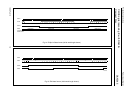
Possible application diagrams are shown in Fig.16.