


1998 Feb 16 25
Philips Semiconductors Product specification
CMOS digital decoding IC with RAM for
Compact Disc
SAA7345
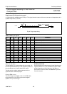
Flags Output (CFLG) (open drain output)
A 1-bit flag signal is available at the CFLG pin. This signal shows the status of the error corrector and interpolator and is
updated every frame (7.35 kHz).
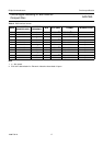
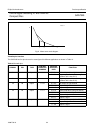
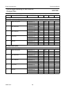
Table 11 Meaning of flag bits.
F1 F2 F3 F4 F5 F6 F7 MEANING
0 X X X X X X no absolute time sync
1 X X X X X X absolute time sync
X 0 0 X X X X C1 frame contained no errors
X 0 1 X X X X C1 frame contained 1 error
X 1 0 X X X X C1 frame contained 2 errors
X 1 1 X X X X C1 frame non-correctable
X X X 0 0 X X C2 frame contained no errors
X X X 0 1 X X C2 frame contained 1 error
X X X 1 0 X X C2 frame contained 2 errors
X X X 1 1 X X C2 frame non-correctable
X X X X X 0 0 no interpolations
X X X X X 0 1 at least one 1-sample interpolation
X X X X X 1 0 at least one hold and no interpolations
X X X X X 1 1 at least one hold and one 1-sample interpolation
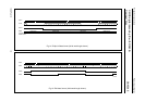
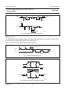
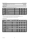
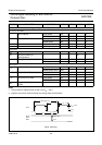
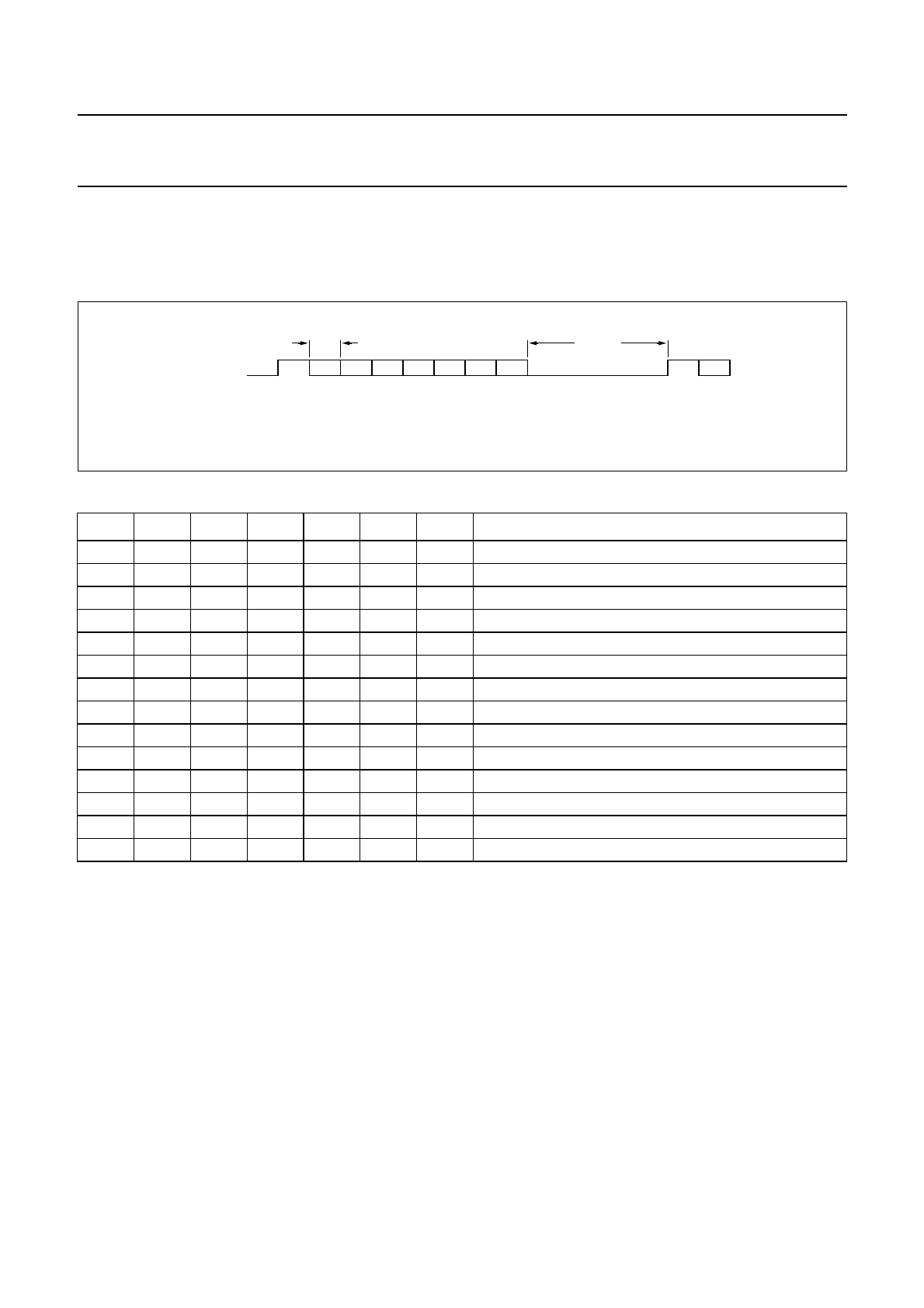
Fig.22 Flags output timing.
handbook, full pagewidth
F1 F2 F3 F4 F5 F6 F7 F1
11.3
µs
45.4 µs
MGA370
CFLG
ABSOLUTE TIME SYNC
The first flag bit (F1) is the absolute time sync signal. It is
the FIFO-passed subcode-sync and relates the position of
the subcode-sync to the audio data (DAC output).
The flag may be used for special purposes such as
synchronization of different players.
F
LAGS AT EBU OUTPUT
The CFLG flags are available on bit 4 of the EBU data
format when bit 3 of the EBU output control register
(address 1010) is set to logic 1.
Double speed mode
Double speed mode is programmed via the Speed control
register (address 1011). It is possible to program double
speed independent of clock frequency, but optimum
performance is achieved with a 33.8688 MHz crystal or a
ceramic resonator.