


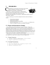
Gripper & Experimenter’s Module
7
3. Installation
lease read through this chapter carefully before you attempt to attach the Gripper
& Experimenter’s Module to your Pioneer 1 Mobile Robot. If for any reason you
do not wish to perform the work yourself, contact RWI and make arrangements to
have the assembly installed at the factory.
On the other hand, skip this chapter altogether if your Pioneer 1 Mobile Robot came
with the Gripper & Experimenter’s Module Assembly already attached.
Turn OFF the Pioneer robot’s Main Power before installing the
Gripper & Experimenter’s Module.
3.1.1 Step 1: Remove the Console
The Gripper & Experimenter’s Module Assembly’s various ports and accessories
connect to the Pioneer microcontroller’s power and expansion I/O. Also, software
support is provided through a special Pioneer Server Operating System (PSOS), which is
stored on a 32K EPROM mounted on the microcontroller. Accordingly, to install the
Gripper/Experimenter’s Module and new PSOS, you must first disassemble the Pioneer
Console.
With one of the hex wrenches that came with your robot, remove the six outermost
screws that secure the top plate to the Console—two on the front (including camera, if
attached) and two on each side.
If one is attached, carefully unplug and remove the Pioneer camera from the Console
and back panel. Also unscrew and remove the radio modem antenna, if attached.
Twist counter-clockwise to remove, and
twist clockwise to insert the various screws.
Gently lift the Console top plate to expose the microcontroller board, which is
mounted to its underside, and the various wire harnesses attached to it. Being careful to
not handle the attached microcontroller card, remove the wire connectors on both sides of
the card from their sockets, freeing the Console top plate with the microcontroller card
attached.
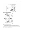
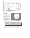
3.1.2 Step 2: Remove Microcontroller from Console
Lay the Console top plate face up, with the Pioneer 1 microcontroller card down, onto
a clean, soft surface (first section of the Sunday Times is a great pad). Locate and remove
the six hex screws—one in each side and two in the middle—which secure the
microcontroller board to the Console top plate. Separate the parts. The microcontroller
board should be exposed now, face-up on the table (Figure 2-1).
P