


Installation
10
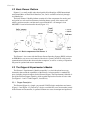
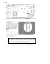
3.1.8 Step 8 Re-Attach the Console Cables
Carefully handling the Console top plate with attached microcontroller by its edges,
reattach the various cables, front and back. Although the order is not critical, for
convenience we recommend attaching the front cables first
the sonar and drive (left and
right) cables.
Then, to the sockets on the rear of the microcontroller, attach the 4-pin serial
connector, the new 16-pin Nose I/O and 26-pin General I/O connectors, and finally the
new power connector to their respective sockets.
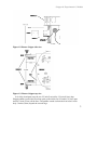
3.1.9 Step 9 Re-Attach the Console
Align the Console top-plate with microcontroller on top the Console, and using the
tools and the screws from Step 2, reattach it to the robot body. Reattach the camera to the
front of the Console as well, if it is with your robot. Then plug the camera power and
signal cables back into their respective sockets on the Console back plate, and screw in
the antenna through the hole in the Console top plate and into the radio modem beneath.
3.1.10 Step 10 Test the Assembly
Time to switch on the Pioneer’s Main Power and sniff for blue smoke. If sparks don’t
fly and smoke is absent, the Pioneer will automatically exercise it’s new Gripper and
finish with three loud and firm beeps through the newly attached speaker—not that weak,
sniveling old “beep, beep” of the Gripper-less Pioneer, mind you, so keep sensitive
babies and weaklings clear.
You’ve completed assembly and now are ready to run your Pioneer’s brand new
gadgets. And for your troubles, you get two loose screws left over (they are the two
round headed ones that came out of the bottom of the Nose).