


9
En
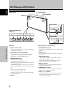
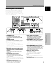
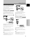
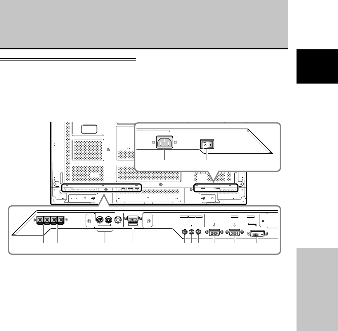
Part Names and Functions
English
COMBINATION
IN OUT
RS-232C
AUDIO AUDIO
INPUT1
AUDIO
OUTPUT INPUT2
ANALOG RGB OUT
(D-Sub)
ANALOG RGB IN
(D-Sub)
INPUT1
DIGITAL RGB
(DVI-D)
INPUT2
4
=-
21 8 9 03567
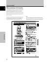
1 SPEAKER (R) terminal
For connection of an external right speaker.
Connect a speaker that has an impedance of 6 Ω
(page 14).
2 SPEAKER (L) terminal
For connection of an external left speaker. Connect a
speaker that has an impedance of 6 Ω (page 14).
3 COMBINATION IN/OUT
Never connect any component to these
connectors without first consulting your Pioneer
installation technician.
These connectors are used for Plasma Display setup
adjustments.
4 RS-232C
Never connect any component to this connector
without first consulting your Pioneer installation
technician.
This connector is used for Plasma Display setup
adjustments.
5 AUDIO (OUTPUT) (Stereo mini jack)
Use to output the audio of the selected source
component connected to this unit to an AV amplifier
or similar component.
Note: No sound is produced from the AUDIO (OUTPUT) jack
when the MAIN POWER switch is set to OFF or ON (standby)
(page 14).
6 AUDIO (INPUT1) (Stereo mini jack)
Use to obtain sound when INPUT1 is selected.
Connect the audio output jack of components
connected to INPUT1 to this unit (page 14).
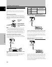
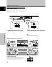
Connection panel (PDP-507CMX)
The connection panel is provided with two video input
terminals and one video output terminal. Audio input/
output and speaker output terminals are also provided.
For instructions regarding connections, consult the pages
noted in parentheses by each item.
7 AUDIO (INPUT2) (Stereo mini jack)
Use to obtain sound when INPUT2 is selected.
Connect the audio output jack of components
connected to INPUT2 to this unit (page 14).
8 ANALOG RGB OUT (INPUT1) (mini D-sub 15 pin)
Use the ANALOG RGB OUT (INPUT1) terminal to
output the video signal to an external monitor or other
component.
Note: The video signal will not be output from the ANALOG
RGB OUT (INPUT1) terminal when the main power of this
unit is off or in standby mode.(page 13)
9 ANALOG RGB IN (INPUT1) (mini D-sub 15 pin)
For connection of a personal computer (PC) or similar
component. Make sure that the connection made
corresponds to the format of the signal output from
the connected component (page 13).
0 DIGITAL RGB (INPUT2) (DVI-D jack)
Use to connect a computer.
Note: This unit does not support the display of
copyguard-protected video signals (page 13).
- AC IN
Use to connect the supplied power cord to an AC
outlet (page 15).
= MAIN POWER switch
Use to switch the main power of the unit on and off.
Part Names and Functions