


10
En
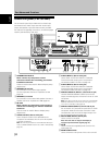
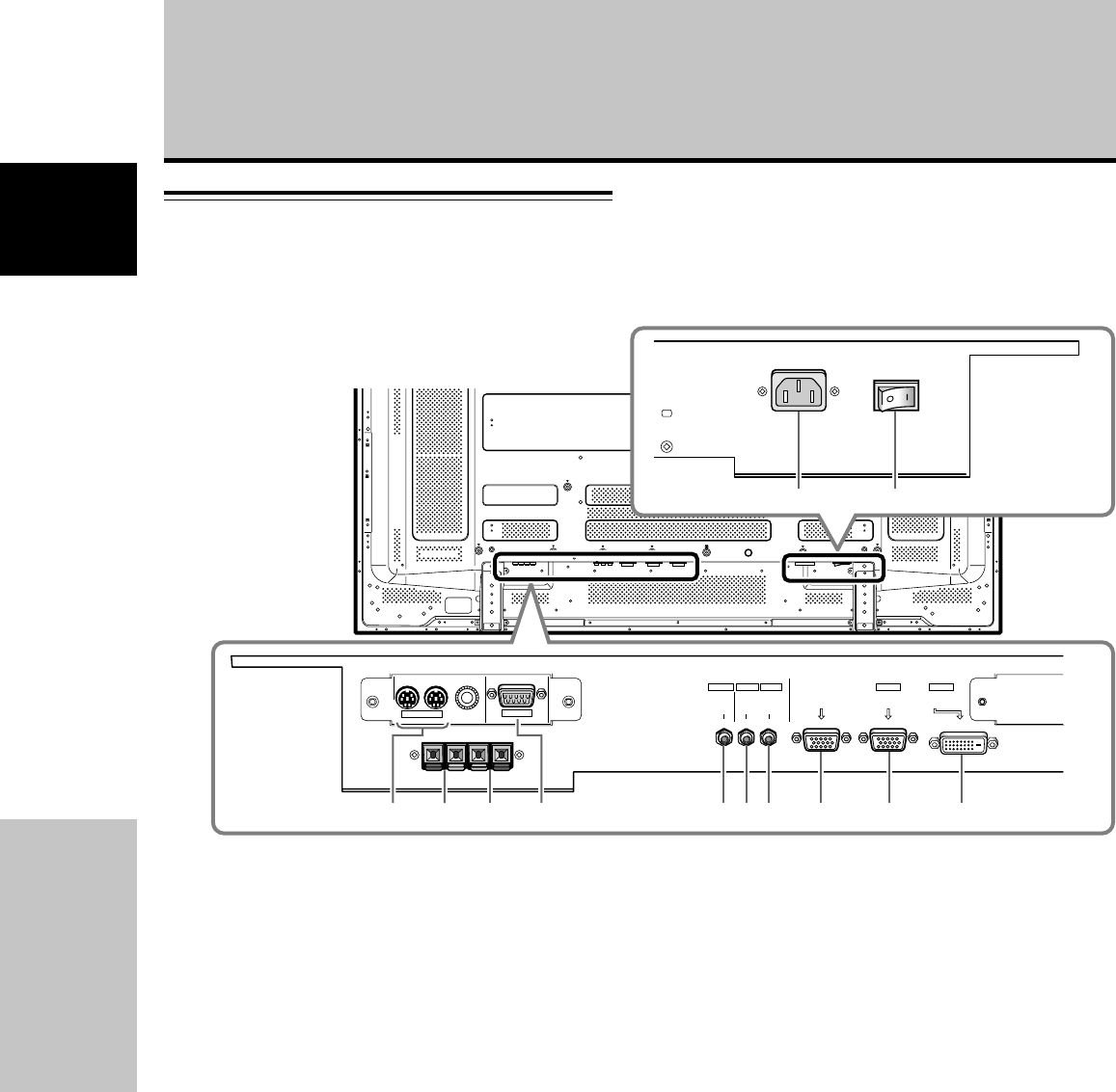
Part Names and Functions
English
COMBINATION
IN OUT
RS-232C
AUDIO AUDIO
INPUT1
AUDIO
OUTPUT INPUT2
ANALOG RGB OUT
(D-Sub)
ANALOG RGB IN
(D-Sub)
INPUT1
DIGITAL RGB
(DVI-D)
INPUT2
0432158967
=-
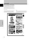
Part Names and Functions
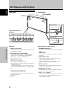
1 COMBINATION IN/OUT
Never connect any component to these
connectors without first consulting your Pioneer
installation technician.
These connectors are used for Plasma Display setup
adjustments.
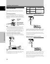
2 SPEAKER (R) terminal
For connection of an external right speaker.
Connect a speaker that has an impedance of 6 Ω
(page 14).
3 SPEAKER (L) terminal
For connection of an external left speaker. Connect a
speaker that has an impedance of 6 Ω (page 14).
4 RS-232C
Never connect any component to this connector
without first consulting your Pioneer installation
technician.
This connector is used for Plasma Display setup
adjustments.
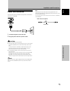
5 AUDIO (OUTPUT) (Stereo mini jack)
Use to output the audio of the selected source
component connected to this unit to an AV amplifier
or similar component.
Note: No sound is produced from the AUDIO (OUTPUT) jack
when the MAIN POWER switch is set to OFF or ON (standby)
(page 14).
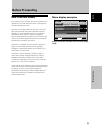
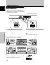
Connection panel (PDP-607CMX)
The connection panel is provided with two video input
terminals and one video output terminal. Audio input/
output and speaker output terminals are also provided.
For instructions regarding connections, consult the pages
noted in parentheses by each item.
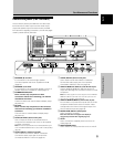
6 AUDIO (INPUT1) (Stereo mini jack)
Use to obtain sound when INPUT1 is selected.
Connect the audio output jack of components
connected to INPUT1 to this unit (page 14).
7 AUDIO (INPUT2) (Stereo mini jack)
Use to obtain sound when INPUT2 is selected.
Connect the audio output jack of components
connected to INPUT2 to this unit (page 14).
8 ANALOG RGB OUT (INPUT1) (mini D-sub 15 pin)
Use the ANALOG RGB OUT (INPUT1) terminal to
output the video signal to an external monitor or other
component.
Note: The video signal will not be output from the ANALOG
RGB OUT (INPUT1) terminal when the main power of this
unit is off or in standby mode.(page 13)
9 ANALOG RGB IN (INPUT1) (mini D-sub 15 pin)
For connection of a personal computer (PC) or similar
component. Make sure that the connection made
corresponds to the format of the signal output from
the connected component (page 13).
0 DIGITAL RGB (INPUT2) (DVI-D jack)
Use to connect a computer.
Note: This unit does not support the display of
copyguard-protected video signals (page 13).
- AC IN
Use to connect the supplied power cord to an AC
outlet (page 15).
= MAIN POWER switch
Use to switch the main power of the unit on and off.