


13
En
Installation and Connections
Français
English
Installation and Connections
Connection to a personal computer
Connection method differs depending on the computer
type. When connecting, please thoroughly read the
computer’s instruction manual.
Before making connections, be sure to make sure that
the personal computer’s power and this unit’s main
power is off.
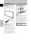
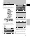
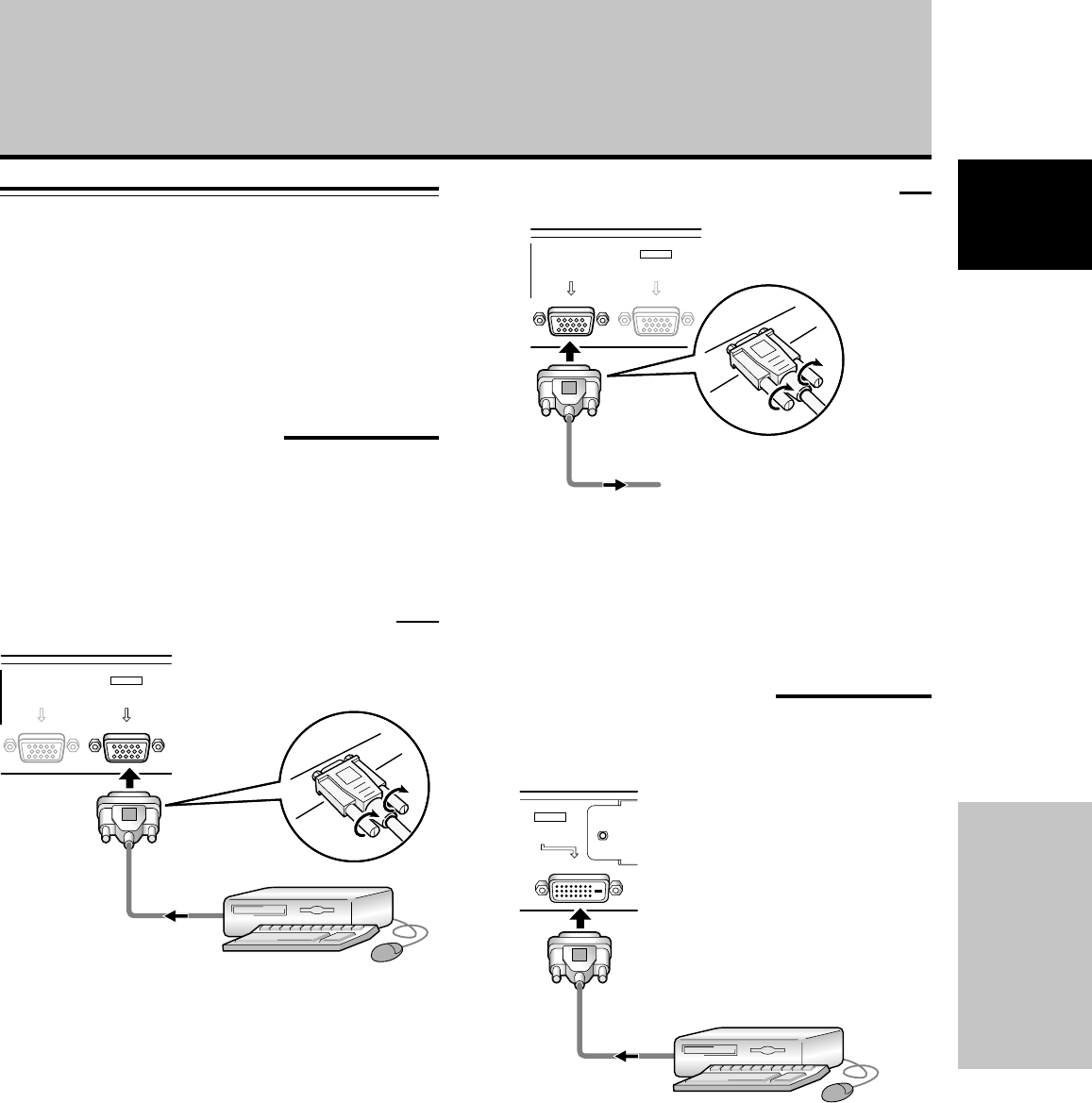
Connection to INPUT1
Connect the display’s D-sub input connector to the D-sub
output (analog RGB) from the computer.
This connector also supports G ON SYNC (output with
green signal combined with sync signal), and composite
SYNC (output with combined horizontal and vertical sync
signals).
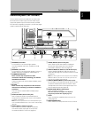
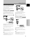
When connecting to ANALOG RGB IN (INPUT1)
ANALOG RGB OUT
(D-Sub)
ANALOG RGB IN
(D-Sub)
INPUT1
Connect the cable corresponding to the shape of the
input terminal on this unit and the personal computer’s
output terminal.
Secure by tightening the terminal screws on both units.
Following completing connections, on-screen setup is
necessary. See pages 17 to 18 for details.
Note
Depending on the type of computer model being connected, a
conversion connector or adapter etc. provided with the computer
or sold separately may be necessary.
For details, please read your PC’s instruction manual or consult
the maker or nearest dealer of your computer.
NOTICE
¶ INPUT1 supports Microsoft “Plug & Play” (VESA DDC 1/2B)
components. See Appendix 2-1/2 (page 45) when making
connections to INPUT1.
¶ See Appendix 1 (pages 42 to 43) for information regarding
signals and display formats supported by INPUT1.
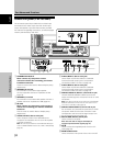
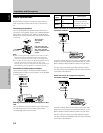
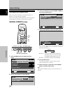
To an external monitor
When connecting to ANALOG RGB OUT (INPUT1)
ANALOG RGB OUT
(D-Sub)
ANALOG RGB IN
(D-Sub)
INPUT1
With this unit, it is possible to output the video signal to
an external monitor or other component from the
ANALOG RGB OUT (INPUT1) terminal.
Note
A video signal will not be output from the ANALOG RGB OUT
(INPUT1) terminal when the main power of this unit is off or in
standby.
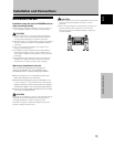
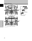
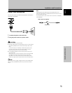
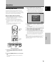
Connection to INPUT2
A computer equipped with DVI output (digital RGB signal)
can be connected to the Plasma Display’s DVI connector.
DIGITAL RGB
(DVI-D)
INPUT2
Following completing connections, on-screen setup is
necessary. See pages 17 to 18 for details.
Notes
¶ Use a DVI-D 24-pin (digital only) cable for the connection.
¶ This unit does not support the display of copyguard-protected
video signals.
NOTICE
¶ INPUT2 supports Microsoft “Plug & Play” (VESA DDC 2B)
components. See Appendix 2-2/2 (page 45) when making
connections to INPUT2.
¶ See Appendix 1 (pages 43 to 44) for information regarding
signals and display formats supported by INPUT2.