3
Chapter 2 Hardware Description
This product series provide three different operating speed – 10Mbps, 100Mbps, and
1000Mbps in the same switch and automatically distinguish the speed of incoming
connection.
This section describes the hardware features of these Switches. For easier management
and control of the switch, familiarize yourself with its display indicators, and ports. Front
panel illustrations in this chapter display the unit LED indicators. Before connecting any
network device to the switch, read this chapter carefully.
There are three choices of different modules for expansion:
l 10/100/1000Base-T module
l 1000Base-SX module
l 1000Base-LX module
2.1 Front Panel
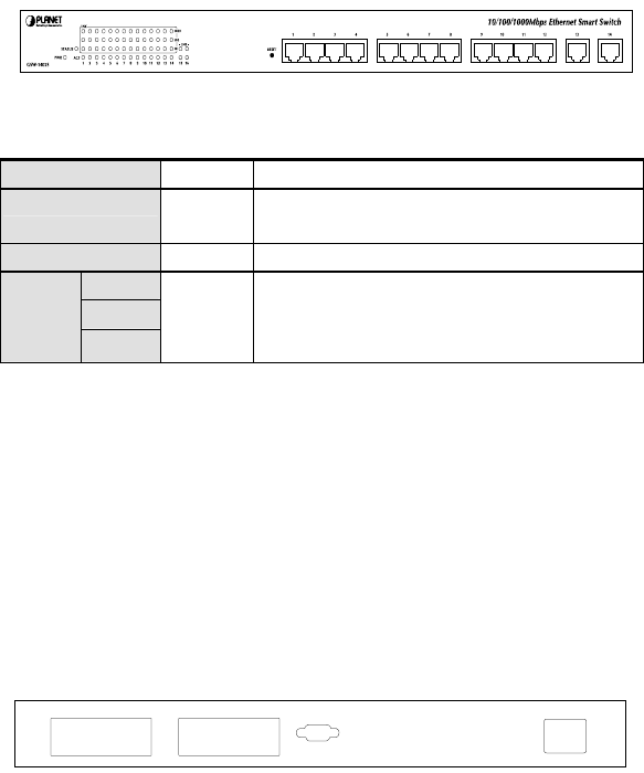
The unit front panel provides a simple interface monitoring the switching hub.
GSW-1402S Switch front panel
LED indicators
PWR Green On: power on
STATUS Green On: System is OK
Blink: Run Time Error occurs
ACT Green Blink: there is traffic transverses the port
10
100
LNK
1000
Green On: indicate link status and traffic s
peed (10
for 10Mbps, 100 for 100Mbps, 1000
for 1000Mbps)
Reset button
At the right side of front panel, the reset button is designed for reconfiguring the switch
without turn off and on the power.
2.2 Rear Panel
The rear panel of the Switch indicates an AC inlet power socket, which accepts input
power from 100 to 240VAC, 50-60Hz, one RS-232 console port for setting up the switch
via a connection to a terminal or PC using a terminal emulation program, and two slide
slots for installing additional modules.
1516
CONSOLE
9600, 8, N, 1
100-240V AC
50-60Hz
GSW-1402S Switch front panel


