


43
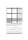
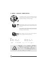
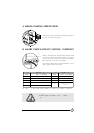
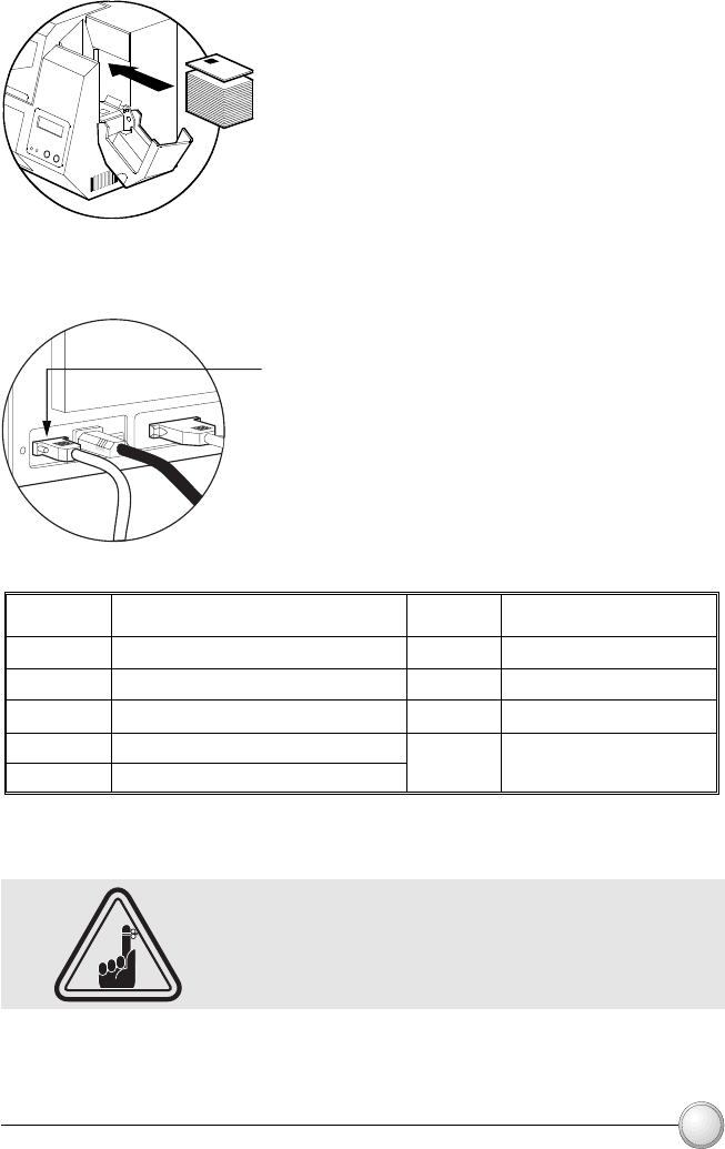
Position the cards with the Smart Card Chip at the top of
the card and towards the printer.
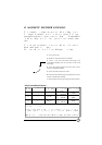
When a command to the parallel printer interface sends
a card to the Smart Card Contact Station, the printer
connects the Smart Card Contact Station to the female
DB-9 connector on the rear of the printer.
An attached external Smart Card Programmer can be
used to program Smart Card chips.
7
8
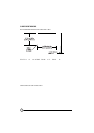
DB - 9
PINS
6
9
C7 (I/O)
C8 (RFU)
SMART CARD
CONTACT POINTS
C6 (Vpp)
(GND when chip is at
station)
C2 (Reset)
C3 (Clock)
SMART CARD
CONTACT POINTS
CI (Vcc)
C4 (RFU)
C5 (GND)
2
3
DB - 9
PINS
1
4
5
Refer to the Card Printer Programmer's Manual for complete programming information.
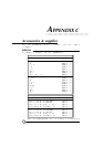
APPENDIX B
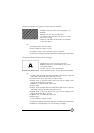
DO NOT position printing over the Smart Card
Chip.
A. MEDIA LOADING ORIENTATION
B. SMART CARD CONTACT STATION INTERFACE