


Operation and Configuration
11
Powerware
®
3115 User’s Guide www.powerware.com
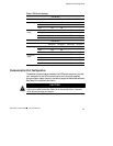
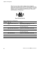
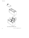
Table 1. DIP Switch Settings
120V Models
DIPSwitch1 DIPSwitch2 DIPSwitch3 DIPSwitch4
Output Voltage
110V ON OFF
p
g
120V* OFF OFF
127V OFF ON
Utility Power
103V - 142V* OFF OFF
y
Range
98V - 142V
ON ON
93V - 142V OFF ON
88V - 142V ON OFF
230V Models
DIPSwitch1 DIPSwitch2 DIPSwitch3 DIPSwitch4
Output Voltage
220V ON OFF
p
g
230V* OFF OFF
240V OFF ON
Utility Power
196V - 260V* OFF OFF
y
Range
186V - 260V
ON ON
176V - 260V OFF ON
166V - 260V ON OFF
*Default position
Communication Port Configuration
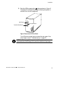
To establish communication between the UPS and a computer, connect
your computer to the UPS communication port using the supplied
communication cable. Use only the factory-supplied cable and software.
See Table 2 for detailed information.
CAUTION
To prevent damage to your equipment, connect only a factory-supplied cable or a cable
built to factory specifications (see Table 2) to the communication port. A standard
serial cable may damage your computer.