


Operation and Configuration
12
Powerware
®
3115 User’s Guide www.powerware.com
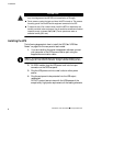
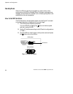
When the communication cable is installed, power management
software can exchange data with the UPS. The software polls the UPS for
detailed information on the status of the power environment. If a power
emergency occurs, the software initiates the saving of all data and an
orderly shutdown of the equipment.
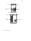
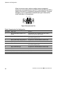
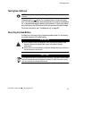
12345
6789
Figure 8. Communication Port
Table 2. Communication Port Configuration
Pin Number Signal Type Function
1 Input: RS-232 high level signal for >0.4
seconds
Conditional Power Off: In absence of AC power, output is
turned off until normal AC power returns
2 Output: Open closing to logic ground pin 4 Impending Low Battery: Indicates the battery has less than 2
to 5 minutes of backup time left
3 Output: Open closing to logic ground pin 4 AC Input Failure: Indicates absence of normal AC input
4 Signal Return Logic Ground
5 Output: RS-232 level low Impending Low Battery: Indicates the battery has less than 2
to 5 minutes of backup time left
6 Output: RS-232 level high AC Input Failure: Indicates absence of normal AC input
7 Not Used Not Used
8 Not Used Not Used
9 Chassis Ground (connected to pin 4) Chassis Ground