4–Hardware Installation
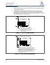
QLE3044 Installation
4-2 NE0154601-00 A
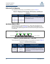
Ethernet Port Mapping
The mapping of port numbers on the QLE3044 is shown in Table 4-1.
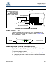
QLE3044 Status LEDs
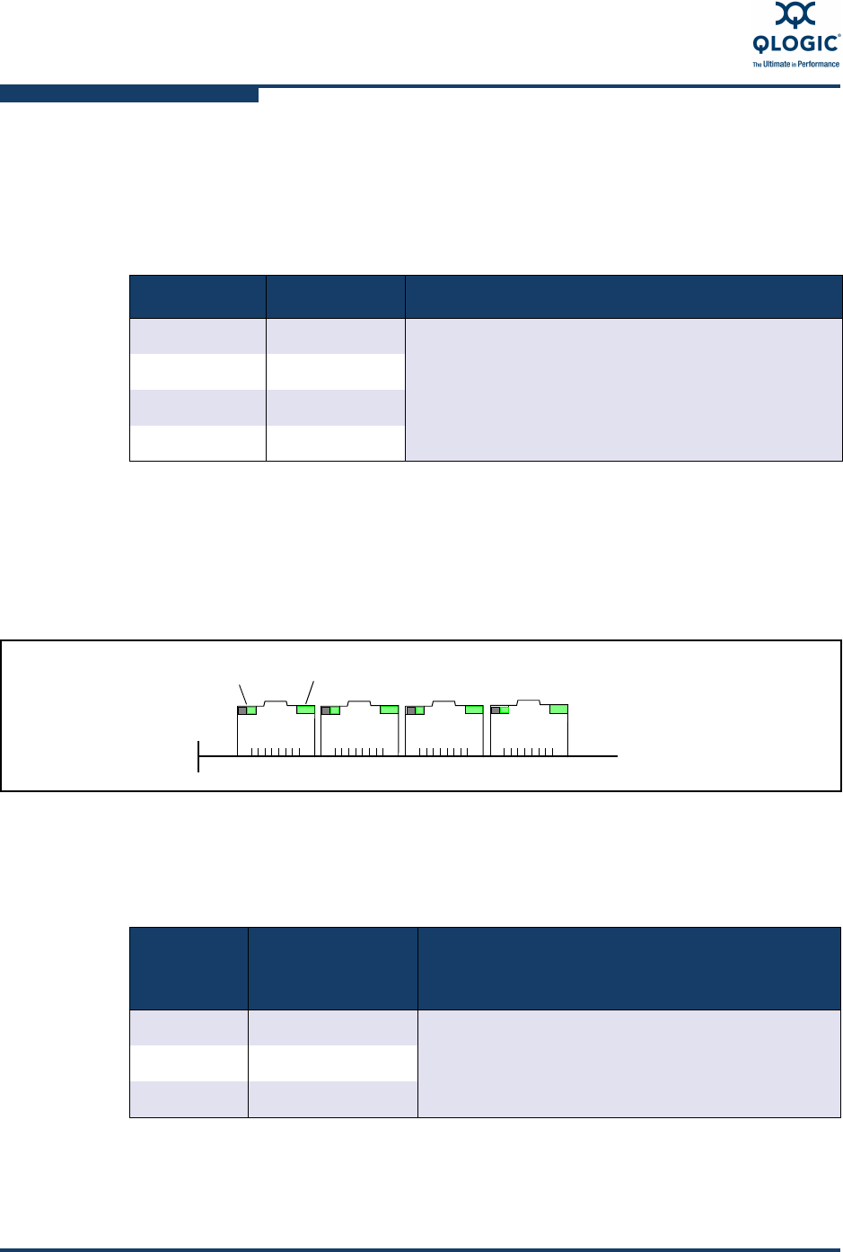
The QLE3044 has two status LEDs per port. These LEDs are located on the
actual port itself as shown in Figure 4-2. When viewing the QLE3044 from the
front, the bi-color green/orange link LED is on the left, and the green activity LED
is on the right.
Figure 4-2. QLE3044 Status LEDs — Front View
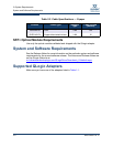
The bi-color link LED indicates the speed of the connection as shown in Table 4-2.
Table 4-1. Mapping of Port Number, PCI Function, and Ethernet
Interface
Port Number PCI Function Ethernet Interface
1 0 Ethernet interface numbers are dynamically allo-
cated by the host. As such, any eth[n] interface can
be connected to any port.
21
3 2
43
Table 4-2. QLE3044 LED Definitions
Speed
Green/Orange
Bi-color Link
LED
Green Activity LED
10 Mbps Off During power-up, the activity LED is on continu-
ously (solid). The LED blinks during normal opera-
tion when there is activity on the port for any of the
speed settings.
100 Mbps Green On
1000 Mbps Orange On
Port 1
Port 2
Port 3
Port 4
Top of board
Bi-color
Link LED
Green
Activity LED
PCIe connector


