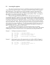
Example 3: Write data into the transmit buffer of channel A.
mov dx, base ; load base address
out dx, al ; write data in ax to buffer
Example 4: Read data from the receive buffer of channel A.
mov dx, base ; load base address
in al, dx ; write data in ax to buffer
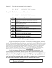
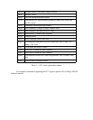
External/Status interrupt information RR15
Upper byte of baud rate time constantRR13
Lower byte of baud rate time constantRR12
Miscellaneous status parameters RR10
Receive buffer RR8
MSB of frame byte count and FIFO status registerRR7
LSB of frame byte count register RR6
Interrupt Pending bits RR3
Modified Channel B interrupt vector and Unmodified
Channel A interrupt vector
RR2
Special Receive Condition status, residue codes, error
conditions
RR1
Transmit, Receive buffer statuses and external status RR0
Table 3 --- SCC read register description
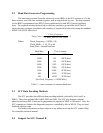
The SCC can perform three basic forms of I/O operations: polling, interrupts, and block
transfer. Polling transfers data, without interrupts, by reading the status of RR0 and then reading
or writing data to the SCC buffers via CPU port accesses. Interrupts on the SCC can be sourced
from the receiver, the transmitter, or External/Status conditions. At the event of an interrupt,
Status can be determined, then data can be written to or read from the SCC via CPU port
accesses. Further information on this subject is found on page 23. For block transfer mode,
DMA transfers are used, so this type of operation is not supported
on the MPAP-100.
The SCC incorporates additional circuitry supporting serial communications. This
circuitry includes clocking options, baud rate generator (BRG), data encoding, and internal
loopback. The SCC may be programmed to select one of several sources to provide the transmit
and receive clocks. These clocks can be programmed in WR11 to come from the RTxC pin, the
TRxC pin, the output of the BRG, or the transmit output of the DPLL. The MPAP-100 uses the
TRxC pin for its clock-on-transmit and the RTxC pin for its clock-on-receive. Programming of
the clocks should be done before enabling the receiver, transmitter, BRG, or DPLL.
Command Register, Register Pointer, CRC initialization, and
resets for various modes
WR0


