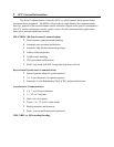
9.2 Baud Rate Generator Programming
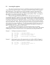
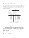
The baud rate generator (hereafter referred to as the BRG) of the SCC consists of a 16-bit
down counter, two 8-bit time constant registers, and an output divide-by-two. The time constant
for the BRG is programmed into WR12 (least significant byte) and WR13 (most significant
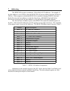
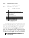
byte). The equation relating the baud rate to the time constant is given below while Table 5
shows the time constants associated with a number of popular baud rates when using the standard
MPAP-100 9.8304 MHz clock.
Time_Const =
Clock_Frequency
2 & Baud_Rate & Clock_Mode
- 2
Where: Clock_Frequency = 9.8304 x 10
6
Clock_Mode = 1, 16, 32, or 64
Baud_Rate = desired baud rate
(for Clock_Frequency = 9.8304 MHz )
3FFE (hex) 16382300
1FFE (hex) 8190600
0FFE (hex) 40941200
07FE (hex) 20462400
03FE (hex) 10224800
01FE (hex) 5109600
00FE (hex) 25419200
007E (hex)12638400
Time ConstantBaud Rate
Table 5 --- time constants for common baud rates
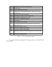
9.3 SCC Data Encoding Methods
The SCC provides four different data encoding methods, selected by bits 6 and 5 in
WR10. These four include NRZ, NRZI, FM1 and FM0. The SCC also features a digital
phase-locked loop (DPLL) that can be programmed to operate in NRZI or FM modes. Also, the
SCC contains two features for diagnostic purposes, controlled by bits in WR14. They are local
loopback and auto echo.
For further information on these subjects or any others involving the SCC contact Zilog
for a complete technical manual.
9.4 Support for SCC Channel B


