


( 26 / 72 )
(1) Using the Oscillator Circuit on the Target System
When turning on the power supply, the internal clock of emulator is selected to supply the clock to
the MCU. To use the external clock on the target system, change the clock by the Init dialog box when
starting up the emulator debugger or the CLK command on the script window (For details, refer to
the user's manual of the emulator debugger).
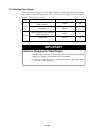
IMPORTANT
Notes on External Clock:
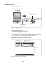
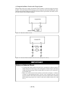
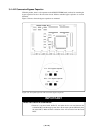
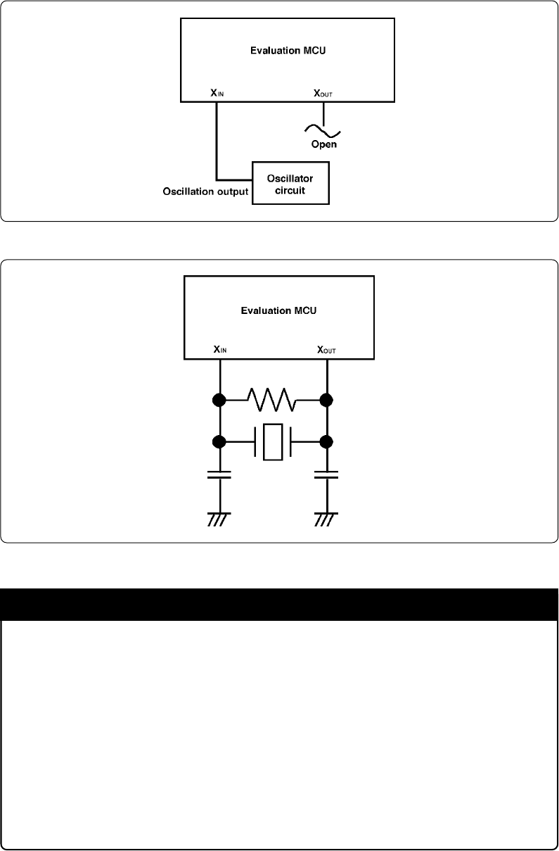
• To operate this product with an external clock, construct the oscillator circuit as
shown in Figure 3.2 in the target system and input the oscillator output at 50% duty
(within the operating range of the evaluation MCU) into the XIN pin. And the XOUT
pin should be open.
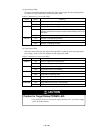
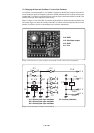
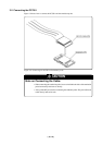
• Make note of the fact that in the oscillator circuit shown in Figure 3.3 where a
resonator is connected between the X
IN and XOUT pins, oscillation does not occur
because a flexible cable, buffer IC and other devices are used between the evaluation
MCU and the target system. It is same for sub-clock oscillator circuits (XCIN and
XCOUT).
Figure 3.2 External oscillator circuit
Figure 3.3 Circuit in which oscillation does not occur (same for X
CIN-XCOUT)