


( 27 / 72 )
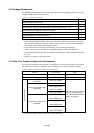
(2) Changing the Internal Oscillator Circuit of the Emulator
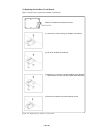
An oscillator circuit board (OSC-3) for 30 MHz is mounted on the PC7501 emulator main unit. To
use the emulation probe at a frequency other than 30 MHz, build the desired oscillator circuit on the
included OSC-2 oscillator circuit board (bare board) and replace the board installed in the PC7501
emulator main unit when shipped from the factory.
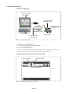
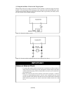
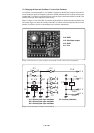
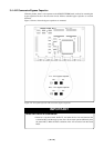
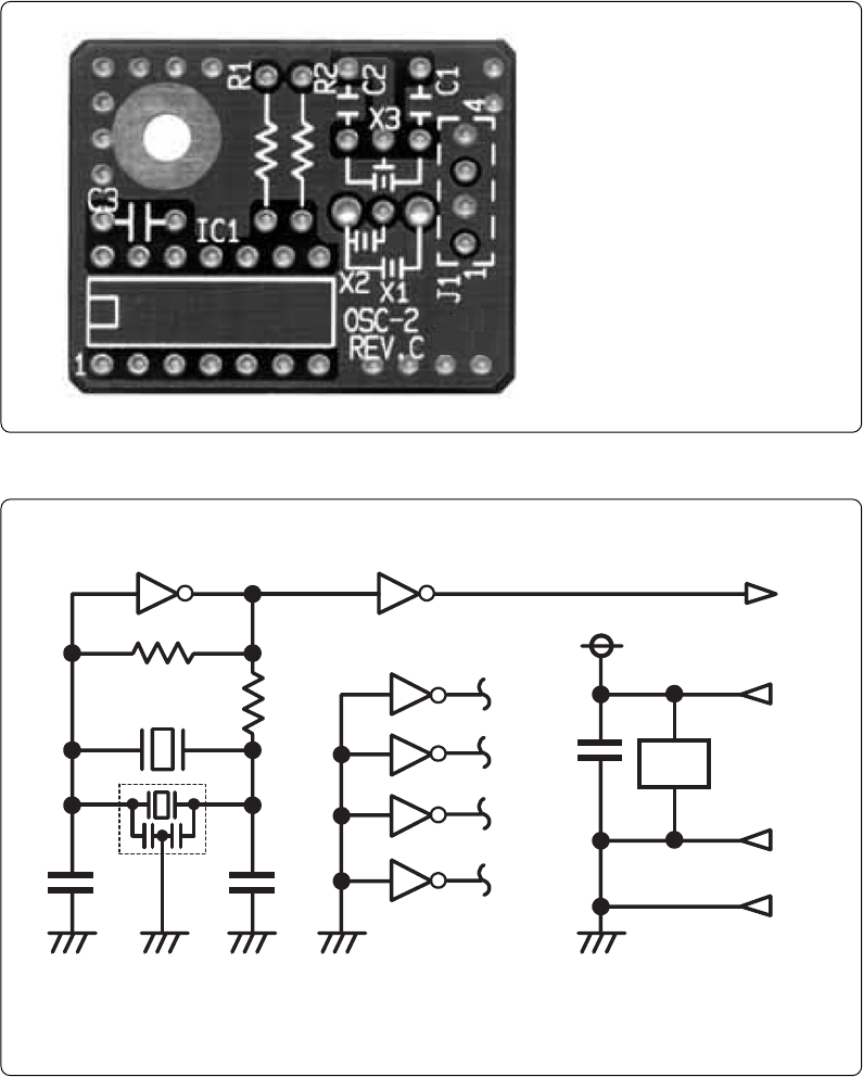
Figure 3.4 shows a view of the OSC-2 oscillator circuit board (bare board) and where connector pins
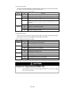
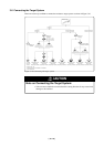
are located. Figure 3.5 shows the circuitry of the OSC-2 oscillator circuit board (bare board). Use the
number of oscillator circuits recommended by the oscillator manufacturer.
Figure 3.4 External view of the oscillator board (OSC-2) and connector pin assignments
J1-4: GND
Figure 3.5 Circuit of the oscillator board (OSC-2)
J1-3: Oscillator output
J1-2: GND
J1-1: Vcc
* X1: 5.08-mm-pitch 2-pin oscillator IC1: Inverter (Unbuffer)
* X2: 2.54-mm-pitch 2-pin oscillator
* X3: 2.54-mm-pitch 3-pin oscillator
IC1
R1
C2
C1
X1 ,X2
CLK
Vcc
GND
R2
J1-3
1011 8
9
2
1
4
3
6
5
12
13
C3
IC1
J1-1
J1-2
J1-4
GND
IC
1
**
X3
*
IC1
14
7