


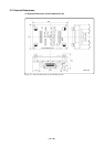
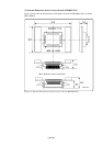
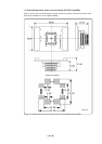

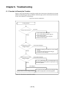


( 65 / 72 )
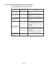
(3) EMEM Dialog Box is Not Displayed When the Emulator Debugger Starts Up
(When the target system is not connected)
Table 6.3 Checkpoints of errors when starting up the emulator debugger (target is not connected)
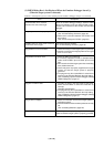
(4) Errors Occur When the Emulator Debugger Starts Up
(When the target system is connected)
Table 6.4 Checkpoints of errors when starting up the emulator debugger (target is connected)
Error
Target MCU is uncontrollable.
Checkpoint
(1) Check the NMI* pin is held high.
(2) If in memory expansion mode or microprocessor
mode, check the RDY* pin and HOLD* pin are held
high.
(3) The program may be uncontrollable in areas where
memory is not allocated. Recheck the map setting.
See "4.3 Starting Up the Emulator Debugger (Setting
EMEM Dialog Box)" (page 47).
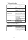
Error
Communication error occurred.
Data was not sent to the target.
Target system cannot be properly built.
PD308F version is not the same version as
the firmware in the target.
Target MCU cannot be reset.
Target is in HOLD state.
Target clock is stopped.
Checkpoint
Check all emulator debugger settings, interface cable
settings and switches on the rear of the PC7501 match.
See the user's manuals of the PC7501 and emulator
debugger.
(1) Download the proper firmware.
See "4.2 Downloading Firmware" (page 46).
(2) Recheck the connection between the PC7501 and
this product.
See "3.5 Connecting the PC7501" (page 33).
Download the proper firmware.
See "4.2 Downloading Firmware" (page 46).
The program may be uncontrollable in areas where
memory is not allocated. Recheck the map setting.
See "4.3 Starting Up the Emulator Debugger (Setting
EMEM Dialog Box)" (page 47).
(1) The MCU is either in the stop mode or wait mode.
Either reset the MCU or cancel the mode with an
interrupt.
See MCU specifications.
(2) The program may be uncontrollable in areas where
memory is not allocated. Recheck the map setting.
See "4.3 Starting Up the Emulator Debugger (Setting
EMEM Dialog Box)" (page 47).
Check the switches in the emulation probe are correctly
set.
See "3.3 Setting Switches" (page 29).