


( 27 / 68 )
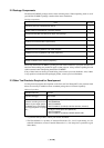
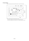
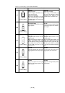
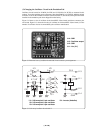
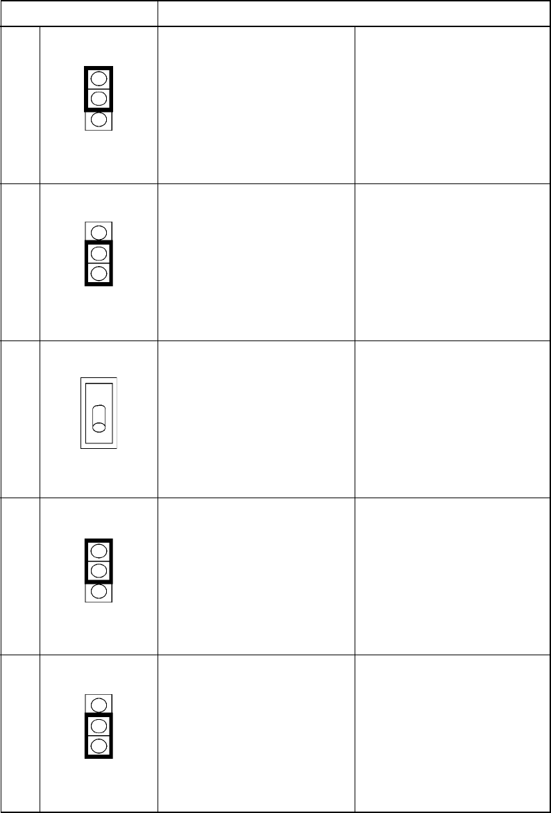
Table 3.1 Switch settings of the M37641T2-RPD-E
Switch setting Description
SW1
P50 side
[Using as a port]
When using pin P50/XCIN as a
port, set to this side.
[Using as a sub-clock]
When using P50/XCIN as a sub-
clock and selecting the XCIN
oscillator circuit on the target board,
set to this side.
XCIN side
[Using as a sub-clock]
When using pin P50/XCIN as a
sub-clock and selecting the XCIN
oscillator circuit OSC-2 in the
emulation pod, set to XCIN side.
SW2
SW7
SW8
SW9
P50
XCIN
(Factory-setting)
NC
P51/XCOUT
(Factory-setting)
P51/XCOUT side
Connects pin XCOUT/P51 to the
target system.
NC side
Does not connects pin XCOUT/P51
to the target system. Pin XCOUT/
P51 is open.
INT
EXT
(Factory-setting)
EXT side
[Using the USB connector on the
target board]
When connecting pins USB D+ and
USB D- via the flexible cable, set to
this side. With this setting, pins USB
D+ and USB D- are not connected
to the USB connector in the
emulation pod.
INT side
[Using the USB connector in the
emulation pod]
When connecting pins USB D+ and
USB D- to the USB connector in the
emulation pod, set to this side. With
this setting, pins USB D+ and USB
D- are not connected to the flexible
cable.
INT
EXT
(Factory-setting)
INT side
Does not output pin Ext. Cap to the
target system. Pin Ext. Cap is open.
EXT side
To connect pin Ext. Cap to the
target system, set to this side.
NC
EXT
(Factory-setting)
NC side
Does not output the clock (pin
XOUT) to the target system. Pin
XOUT is open.
EXT side
Outputs the clock (pin XOUT) to the
target system.