


( 28 / 68 )
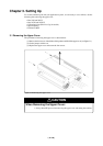
3.4 Connecting USB-related Signals
This section explains emulation pod specifications for each USB-related pin.
(1)Pins D+ and D-
In the factory-setting, electrical characteristics differ from those of the actual MCU because of
the flexible cable between the emulation MCU and target system. If there are problems with
electrical characteristics because of the flexible cable, the USB connector on the emulation pod
can be used.
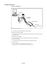
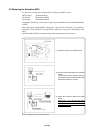
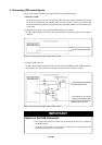
• Connecting to the target system via the flexible cable (factory-setting)
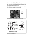
Set SW7 of the emulation pod to EXT side. The connection to the target system is shown in Figure
3.4 below.
Figure 3.4 Connecting pins D+ and D- (SW7 = EXT)
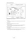
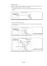
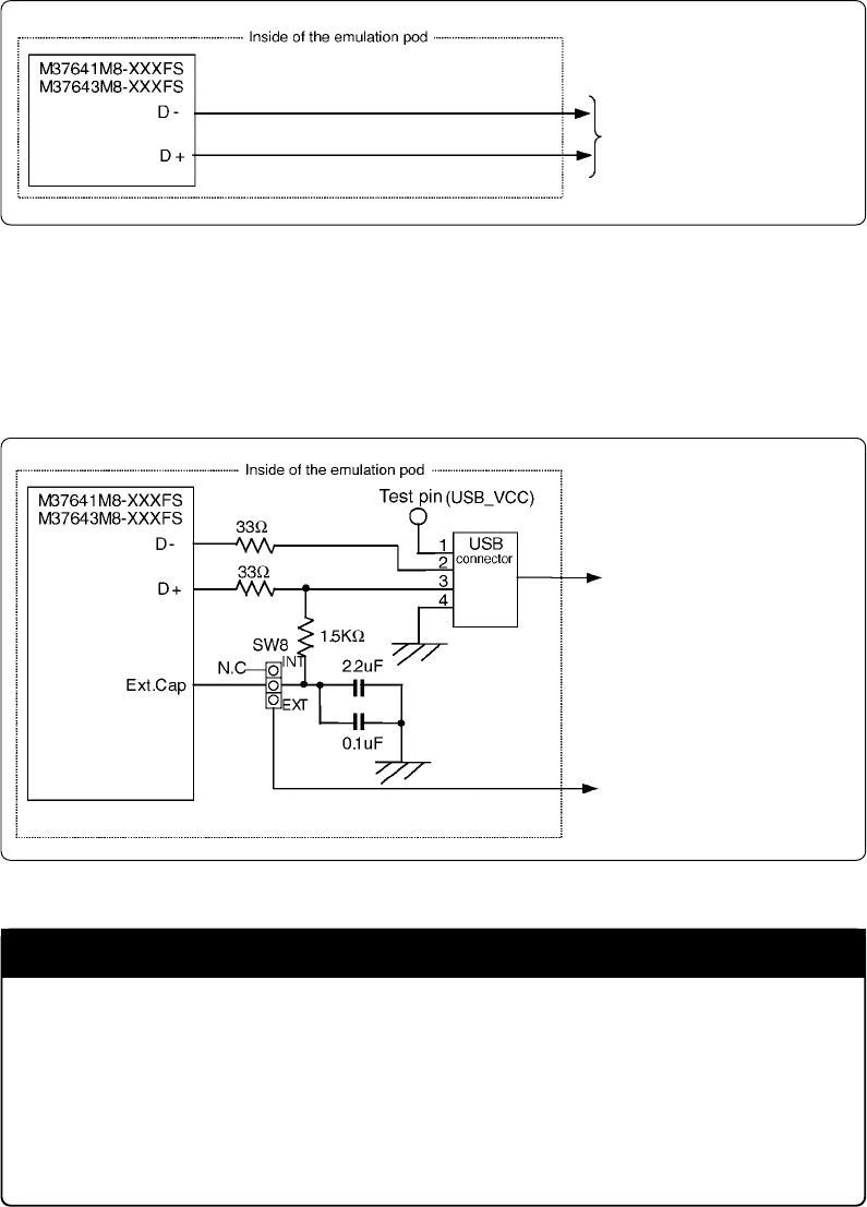
• Using the USB connector
Set SW7 of the emulation pod to INT side. Then, connect the USB cable to the USB connector in
the emulation pod. The connection to the target system is shown in Figure 3.5 below.
Figure 3.5 Connecting pins D+ and D- (SW7 = INT)
Connected to the target
system via the flexible cable
Connected to the target system
via the USB connector
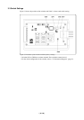
Connected to the target
system via the flexible cable
(cannot be connected when
SW8 is set to INT side)
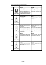
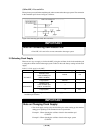
IMPORTANT
Notes on the USB Connector:
• Pin 1 of the USB connector connects only to the test pin (USB_VCC) located near
the USB connector.
•When the USB connector is used, pins D+ and Ext. Cap are connected in the
emulation pod through a 1.5K resistance.