


( 11 / 52 )
IMPORTANT
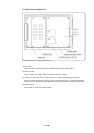
Notes on EMEM Dialog:
• When setting the EMEM dialog box of the emulator debugger M3T-PD79, pay attention to the
following:
(1) Processor Mode
Specify a processor mode for the target MCU to be debugged. If the BYTE pin and MD0 pin
settings do not match the specified processor mode, M3T-PD79 outputs an error message. In
such a case, check the pin settings on the target system.
(2) Emem Address
Allocate the 1MB emulation memory that is included in the emulation pod. However, when
debugging in single-chip or memory expansion mode, emulation memory is automatically
allocated as a work area for spaces corresponding to flash ROM. Therefore, the usable
emulation memory size varies with the internal flash ROM capacity of the selected MCU.
Example: For MCUs with 512KB flash ROM
=> Emulation memory size = 768 KB (256 KB is used as work area)
* 256 KB of emulation memory in banks 0 to 3 cannot be allocated.
(3) ROM Address
Disable the allocated emulation memory against writes by the user program. RAMs that have
been mapped to external locations cannot be disabled against writes.
(4) DMA Address
In this dialog box, set a transfer area when using the MCU's DMA function, and executing 1-
bus transfer between emulation memory and the target system.
(5) 8-bit bus mode Address
When accessing external data buses in 8-bit width using the chip select wait controller when
BYTE pin = Low, set this address for the relevant area.
(6) Map Address
Set external or internal for the allocated emulation memory area.
EXTERNAL:Devices on the target system can be accessed.
INTERNAL: Emulation memory can be accessed.