


( 22 / 52 )
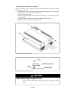
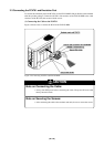
(2) Changing the Internal Oscillator Circuit of the Emulation Pod
An oscillator circuit board for 20 MHz is mounted on this product and an oscillator circuit board for
26 MHz is included. To use the emulation pod at a frequency other than 20 MHz and 26 MHz, build
the desired oscillator circuit on the included OSC-2 oscillator circuit board (bare board) and replace
the board installed in the emulation pod when shipped from the factory.
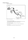
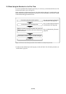
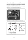
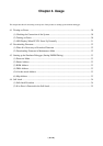
Figure 3.3 shows a view of the OSC-2 oscillator circuit board (bare board) and where connector pins
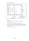
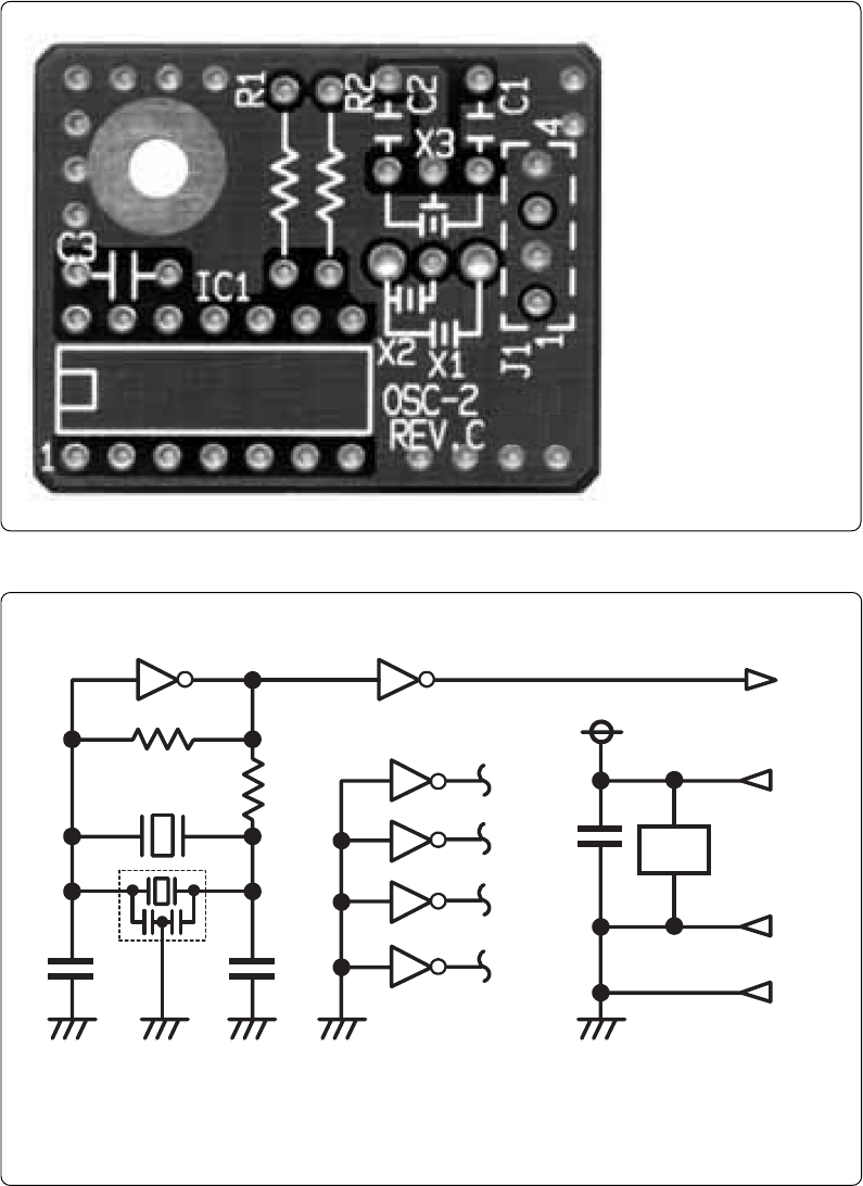
are located. Figure 3.4 shows the circuitry of the OSC-2 oscillator circuit board (bare board). Use the
number of oscillator circuits recommended by the oscillator manufacturer.
Figure 3.3 External view of the oscillator board (OSC-2) and connector pin assignment
J1-4: GND
Figure 3.4 Circuit of the oscillator board (OSC-2)
J1-3: Oscillator output
J1-2: GND
J1-1: Vcc
IC1
R1
C2
C1
X1 ,X2
CLK
Vcc
GND
R2
J1-3
1011 8
9
2
1
4
3
6
5
12
13
C3
IC1
J1-1
J1-2
J1-4
GND
IC
1
**
X3
*
IC1
14
7
* X1: 5.08-mm-pitch 2-pin oscillator IC1: Inverter (Unbuffer)
* X2: 2.54-mm-pitch 2-pin oscillator
* X3: 2.54-mm-pitch 3-pin oscillator