


( 17 / 52 )
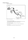
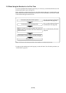
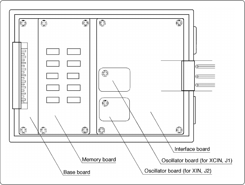
(2) Inside of the Emulation Pod
Figure 2.2 Internal view of the emulation pod
(1) Base board
Base board which controls the interface with the PC4701 and the emulator MCU.
(2) Memory board
Board on which the 1 MB + 256 KB emulation memory is mounted.
(3) Oscillator circuit board (Xin = 20 MHz and Xcin = 32 kHz when shipped from factory)
Board on which the internal oscillator circuit of the emulation pod is mounted. Operating
frequency can be changed by replacing this board with other available oscillator circuit boards.
(4) Interface board
Board which is connected to the pod probe.