


6
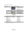
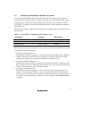
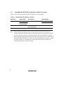
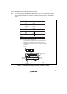
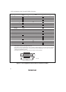
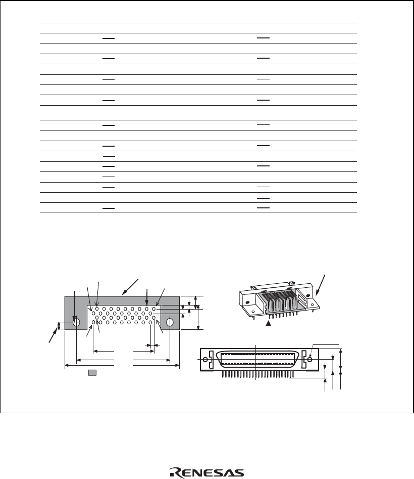
(1) Pin Assignments of the 36-pin H-UDI Port Connector
Note: The signal names are standard for the SH7200 series MCU. For the pin names of MCUs
and recommended circuits for connection, ask Renesas Technology Corp. via the sales
office.
1. Input to or output from the user system.
2. The symbol (#) means that the signal is active-low.
Notes:
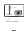
H-UDI port connector
(Pin 1 mark)
(top view)
Unit: mm
4.8
M2.6
x
0.45
9.0
0.3
3.9
H-UDI port connector (front view)
3. The emulator monitors the GND signal of the user system and detects whether or not the user system
is connected.
Pin
No.
Signal
Input/Output
Note
AUDSYNC#
N.C.
N.C.
TCK
GND
AU DATA 0
GND
AU DATA 1
GND
GND
GND
GND
GND
GND
GND
AU DATA 2
AU DATA 3
UVCC
TMS
RES#
GND
GND
TRST#
(GND)
TDI
GND
GND
GND
GND
GND
GND
GND
TDO
ASEBRKAK#
/ ASEBRK#
Input
Input
User reset
Input
Input
Output
Input/
output
Output
Output
Output
Output
Output
Output
Output
Output
Output
1
2
3
4
5
6
7
8
9
10
11
12
13
14
15
16
17
18
19
20
21
22
23
24
25
26
27
28
29
30
31
32
33
34
35
36
Pin
No.
Signal
Input/Output
Note
*1
*1
*2
*4
*2
*2
*2
*3
AUDCK
N.C.
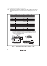
: Pattern inhibited area
Edge of the board
(connected to the connector)
0.7
+0.1
0
2
1.27
1
3
4.5
1.1
1.905
9.0
21.59
37.61
43.51
36
35
4
2.8
+0.1
0
φ
4.09
H-UDI port connector (top view)
φ
4. When the user system interface cable is connected to this pin and the ASEMD# pin is set to 0, do not
connect to GND but to the ASEMD# pin directly.
Figure 1.2 Pin Assignments of the H-UDI Port Connector (36 Pins)