


8
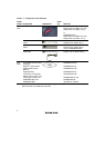
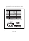
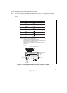
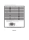
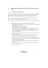
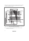
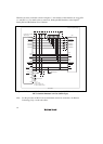
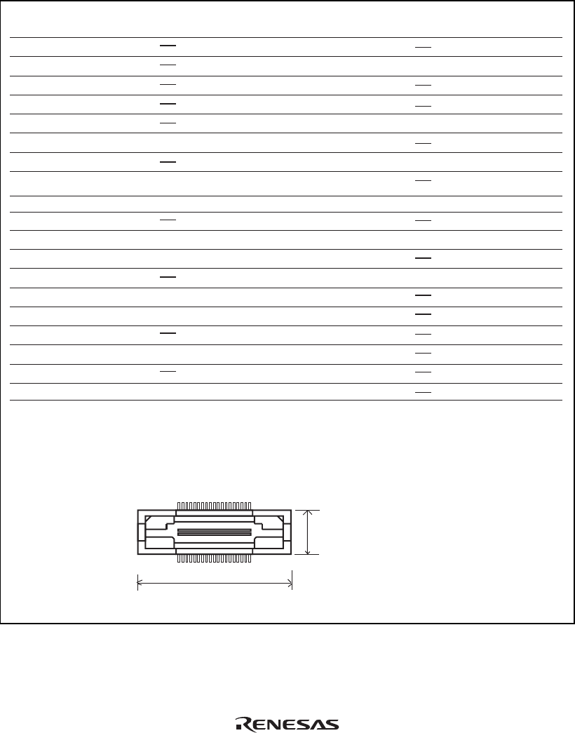
(3) Pin Assignments of the 38-pin H-UDI Port Connector
N.C.
N.C.
ASEMD# (GND)
TCK
N.C.
AUDSYNC#
N.C.
N.C.
AUDATA0
AUDATA1
UVCC_AUD
N.C.
N.C.
TMS
UCON# (GND)
N.C.
AUDCK
UVCC
N.C.
N.C.
RES#
TDI
H-UDI port connector (top view)
Unit: mm
TDO
Output
Output
Input/
Output
Output
Output
Output
Output
Output
Output
Output
Output
Input
Input
Input
Input
1
2
3
4
5
6
7
8
9
10
11
12
13
14
15
16
17
18
20
21
22
23
24
25
26
27
28
29
30
31
32
33
34
35
36
37
N.C.
N.C.
TRST#
ASEBRKAK#/
ASEBRK#
N.C.
AUDATA3
N.C.
AUDATA2
N.C.
N.C.
N.C.
N.C.
N.C.
N.C.
N.C.
19
38
137
38 2
6.91
25.4
Pin
No.
Signal
Input/
Output
Note
Pin
No.
Signal
Input/
Output
Note
*1
*1
*4
*3
*2
*2
*2
Notes:
1. Input to or output from the user system.
2. The symbol (#) means that the signal is active-low.
3. The emulator monitors the GND signal of the user system and detects whether or not the user system is connected.
4.
When the user system interface cable is connected to this pin and the ASEMD# pin is set to 0, do not connect to
GND but to the ASEMD# pin directly.
5. The GND bus lead at the center of the H-UDI port connector must be grounded.
User reset
Figure 1.4 Pin Assignments of the H-UDI Port Connector (38 Pins)