


11
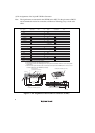
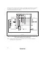
1.5.2 Recommended Circuit (14-Pin Type)
The connection between the H-UDI port connector and MCUs differs according to the internal
circuits of the MCU in use. The following shows an example, however, ask Renesas Technology
Corp. via the sales office for the pull-up, pull-down, and required logic ICs.
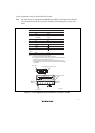
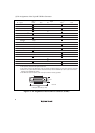
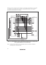
Figure 1.6 shows a recommended circuit for connection between the H-UDI port connector (14
pins) and the MCU when the emulator is in use.
Notes: 1. The sections indicated by dotted lines in the figure are examples and may require logic
ICs.
2. Do not connect anything to the N.C. pins of the H-UDI port connector.
3. The ASEMD# pin must be 0 when the emulator is connected and 1 when the emulator
is not connected, respectively.
(1) When the emulator is used: ASEMD# = 0
(2) When the emulator is not used: ASEMD# = 1
Figure 1.6 shows an example of circuits that allow the ASEMD# pin to be GND (0)
whenever the emulator is connected by using the user system interface cable.
When the ASEMD# pin is changed by switches, etc., ground pin 9. Do not connect
this pin to the ASEMD# pin.
4. When a network resistance is used for pull-up, it may be affected by a noise. Separate
TCK from other resistances.
5. The pattern between the H-UDI port connector and the MCU must be as short as
possible. Do not connect the signal lines to other components on the board.
6. The signal names in the figure mean the standard signals and may differ according to
the MCU in use.
7. For the pin processing in cases where the emulator is not used, refer to the hardware
manual of the related MCU.