


7
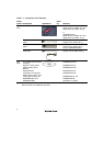
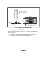
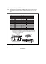
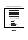
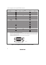
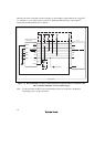
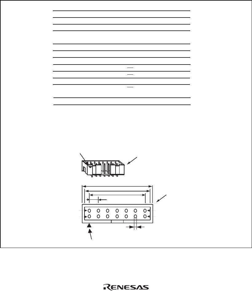
(2) Pin Assignments of the 14-pin H-UDI Port Connector
Note: The signal names are standard for the SH7200 series MCU. For the pin names of MCUs
and recommended circuits for connection, ask Renesas Technology Corp. via the sales
office.
Pin 1 mark
Notes:
1. Input to or output from the user system.
2. The symbol (#) means that the signal is active-low.
3. The emulator monitors the GND signal of the user system and detects
whether or not the user system is connected.
25.0
23.0
6 x 2.54 = 15.24
(2.54)
0.45
Pin 1
Pin 8
Pin 7
Pin 14
Pin 1 mark
H-UDI port connector
(top view)
H-UDI port connector
(top view)
Pin No. Signal
1
2
3
4
5
6
7
8
9
11
10, 12,
and 13
14
TCK
TRST#
TDO
ASEBRKAK#
/ ASEBRK#
TMS
TDI
RES#
N.C.
(GND)
UVCC
GND
Input/Output*
1
*2
*2
GND
*3
Output
Input
Input
Output
Input/
output
Input
Input
Output
Output
4.
When the user system interface cable is connected to this pin and
the ASEMD# pin is set to 0, do not connect to GND but to the ASEMD#
pin directly.
Note
User reset
*2
*4
Unit: mm
Figure 1.3 Pin Assignments of the H-UDI Port Connector (14 Pins)