


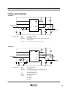
RV5VH1××/RV5VH2××
20
VSEN
DOUT
RV5VH1××/RV5VH2××
Pull-up
Output Tr.
–
+
Vref
Ra
Rb
Rc
Tr.1
2
8
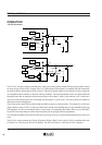
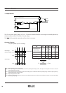
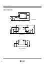
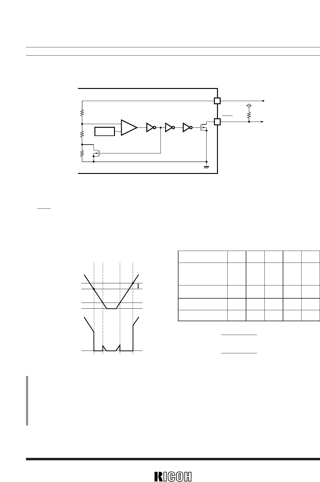
The VD can operate by the voltage of “VOUT1”. The detector threshold and the reset voltage are internally adjusted by
trimmed resistors and the VD monitors V
SEN pin voltage.
The D
OUT is Nch-opendrain output and a pull up resistor is necessary.
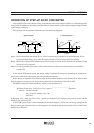
Oepration Diagram
V
SEN pin is pulled up to VOUT1 voltage
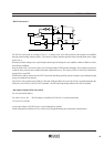
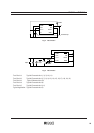
• Voltage Detector
A
B
Reset Voltage
Detector Threshold
GND
GND
Output Voltage
1 2 3 4 5
Hysteresis Range
+VDET
–V
DET
Step Step 1 Step 2 Step 3 Step 4 Step 5
Comparator(+) Pin
Input Voltage
A B B B A
Comparator Output
H L L L H
Tr. 1 OFF ON ON ON OFF
Output Tr
OFF ON
Indefinite
ON OFF
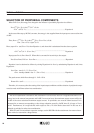
A :
Rb+Rc
×
VSEN
Ra+Rb+Rc
B :
Rb
×
V
SEN
Ra+Rb+Rc
Step 1. Output Voltage is equal to Pull-up Voltage.
Step 2. When Input voltage (V
SEN) reaches the state of Vref≥VSEN×(Rb×Rc)/(Ra+Rb+Rc) at point A, the output of the comparator is reversed. so that the
output voltage becomes to GND.
Step 3. Output VoItage becomes indefinite when Power source Voltage (V
SEN) is smaller than Minimum Operating VoItage. When the output is pulIed up,
Output becomes pull-up voltage and GND.
Step 4. Output VoItage becomes to GND.
Step 5. When input voltage(V
SEN) reaches the state of Vref≤VSEN×Rb/(Ra+Rb) at point B, the output of the comparator is reversed, so that the output voltage
becomes to pull-up voltage.