


3
RV5VH1××/RV5VH2××
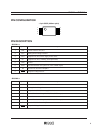
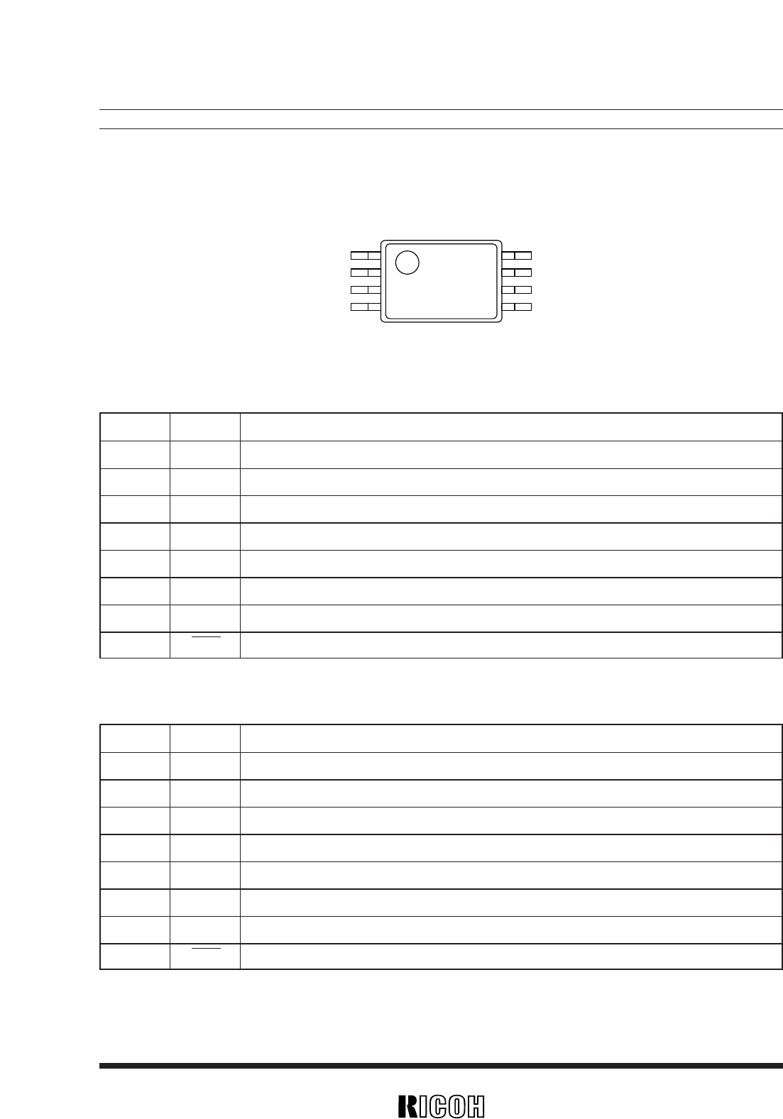
PIN CONFIGURATION
1
2
3
4
8
7
6
5
• 8 pin SSOP (0.65mm pitch)
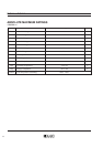
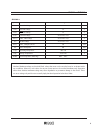
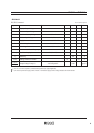
PIN DESCRIPTION
• RV5VH1××
Pin No. Symbol Description
1 CSW Control switch for DC/DC2
2 VSEN Sensing Pin for Voltage Detector
3 VOUT1 Output for DC/DC1, Power supply for the device
4 LX1 Output for DC/DC1, switching (Nch Open-Drain)
5 GND Ground
6 EXT2 External Transistor drive pin for DC/DC2 (CMOS output)
7 FB Input for DC/DC2 Error Amplifier
8 D
OUT Output for Voltage detector
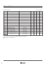
• RV5VH2××
Pin No. Symbol Description
1 CSW Contol switch for DC/DC2
2 VSEN Sensing Pin for Voltage Detector
3 VOUT1 Output for DC/DC1, Power supply for the device
4 EXT1 External Transistor drive pin for DC/DC1 (CMOS output)
5 GND Ground
6 EXT2 External Transistor drive pin for DC/DC2 (CMOS output)
7 FB Input for DC/DC2 Error Amplifier
8 D
OUT Output for Voltage Detector