


21
RV5VH1××/RV5VH2××
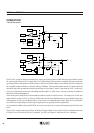
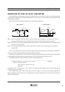
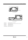
OPERATION OF STEP-UP DC/DC CONVERTER
Step-up DC/DC Converter charges energy in the inductor when Lx Transistor (LxTr) is on, and discharges the
energy with the addition of the energy from Input Power Source thereto, so that a higher output voltage than the
input voltage is obtained.
The operation will be explained with reference to the following diagrams :
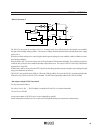
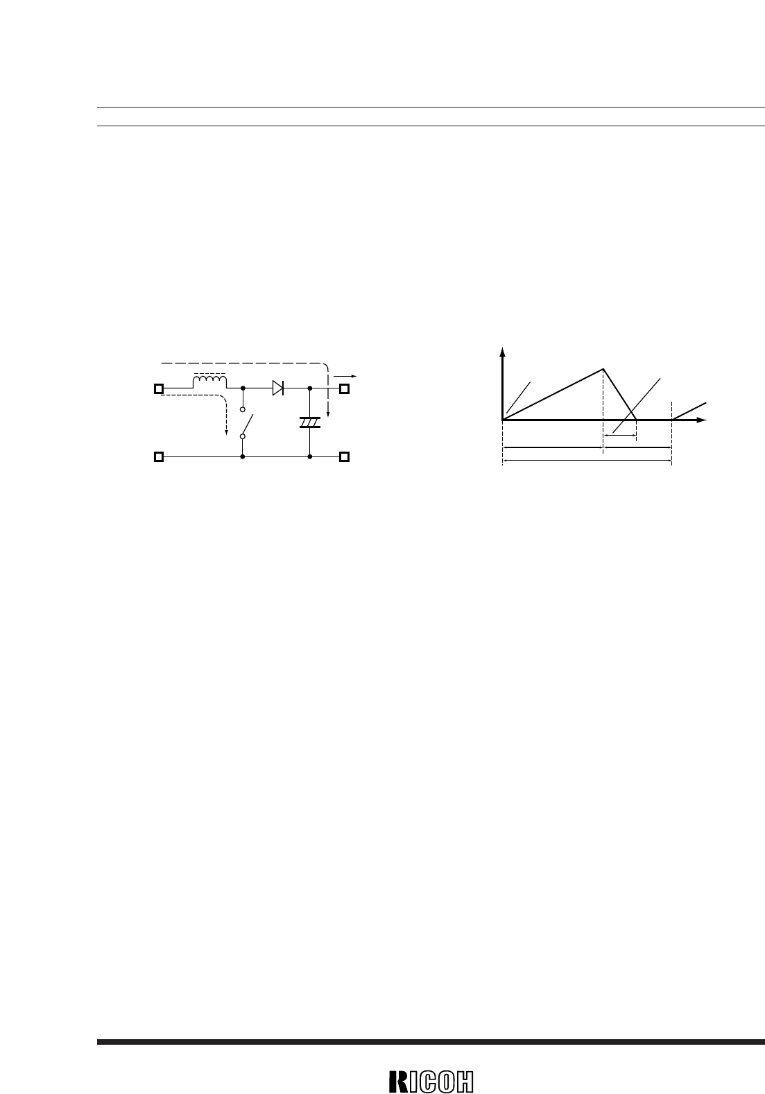
< Current through L >< Basic Circuits >
i2
L
SD
I
OUT
VOUT
CLLx Tr
i1
V
IN
IL
ILmin
ILmax
topen
t
ton
toff
T=1/fosc
Step 1 : LxTr is turned ON and current IL (=i1 ) flows, so that energy is charged in L. At this moment, IL(=i1 )
is increased from ILmin (=0) to reach ILmax in protection to the on-time period (ton) of LxTr.
Step 2 : When LxTr is turned OFF, Schottky diode (SD) is turned on in order that L maintains IL at ILmax, so that
current IL (=i2) is released.
Step 3 : IL (=i2) is gradually decreased, and IL reaches ILmin (=0) after a time period of topen, so that SD is
turned OFF.
In the case of VFM control system, the output voltage is maintained constant by controlling the oscillator fre-
quency (fosc) with the on-time period (ton) being maintained constant.
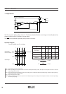
In the above two diagrams, the maximum value (ILmax) and the minimum value (ILmin) of the current which
flows through the inductor are the same as those when LxTr is ON and also when LxTr is OFF.
The difference between ILmax and ILmin, which is represented by ∆I, is:
∆I=ILmax–ILmin=V
IN · ton/L=(VOUT–VIN) · topen/L
..........................................
Equation 1
wherein T=1/fosc=ton+toff
duty (%)=ton/T · 100=ton · fosc · 100
topen≤toff
In Equation 1,V
IN · ton/L and (VOUT–VIN) · topen/L are respectively the change in the current at ON, and the
change in the current at OFF.
In the VFM system, topen < toff as illustrated in the above diagram. In this case, the energy charged in the
inductor during the time period of ton is discharged in its entirely during the time period of toff, so that ILmin
becomes zero (ILmin=0).