


15
2007 RuggedCom Inc. All rights reserved Rev100
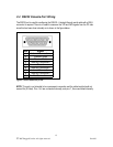
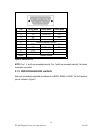
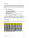
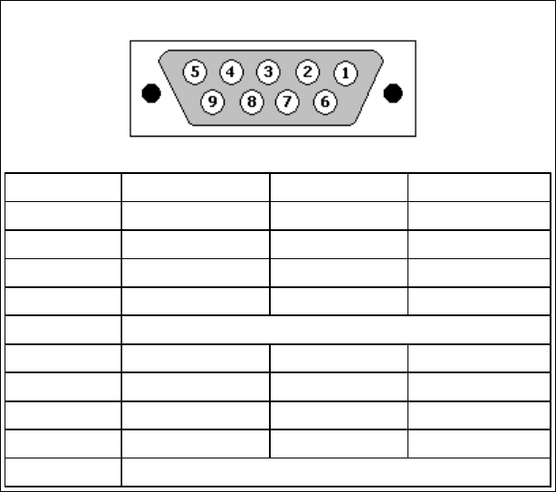
Pin RS232 Mode RS485 Mode RS422 Mode
1 CD - -
2 TX TX/RX+ (A) TX+
3 RX - RX+
4 DTR - -
5
6 DSR - RX-
7 CTS TX/RX - (B) TX-
8 RTS -
9 RI (NC) - -
Shield
Common (Isolated Ground)
Chassis Ground
Figure 10: DB9 Port pin-out
NOTE: Pins 1, 4, and 6 are connected internally. Pins 7 and 8 are connected internally. No internal
termination is provided.
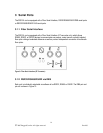
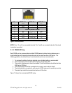
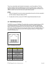
3.1.3 RS232/RS485/RS422 via RJ45
Each port is individually selectable via software to be RS232, RS485 or RS422. The RJ45 port and
pin-out is shown in Figure 11.