


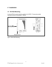
16
2007 RuggedCom Inc. All rights reserved Rev100
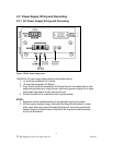
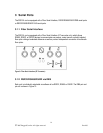
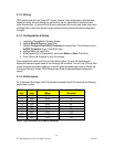
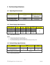
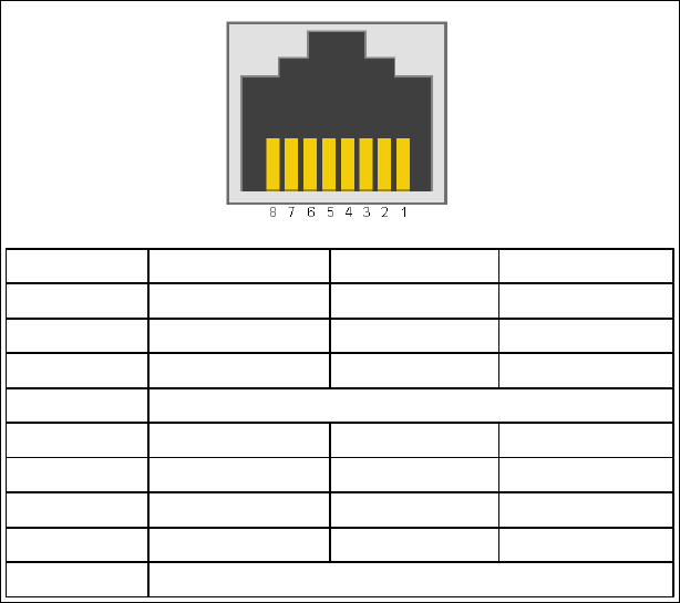
Pin RS232 Mode RS485 Mode RS422 Mode
1 DSR - RX-
2 DCD - -
3 DTR - -
4
5 RX - RX+
6 TX TX/RX + (A) TX +
7 CTS - -
8 RTS TX/RX - (B) TX -
Shield
Common (Isolated Ground)
Chassis Ground
Figure 11: RJ45 Port pin-out
NOTE: Pins 1, 2, and 3 are connected internally. Pins 7 and 8 are connected internally. No internal
termination is provided.
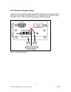
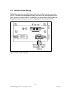
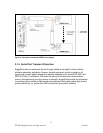
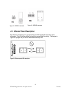
3.1.4 RS485 Wiring
Each RS485 port can communicate to multiple RS485 devices by daisy chaining devices over a
single twisted pair with transmit and receive signals on the same two wires (half duplex). The
following guidelines should be followed to ensure reliable continuous communication:
1. To minimize the effects of ambient electrical noise, shielded cabling is recommended
2. The correct polarity must be observed throughout a single daisy chain
3. The number of devices wired should not exceed 32, and total distance should be less than
4000 feet (at 100Kbps)
4. The COM terminals should be connected to the common wire inside the shield.
5. The shield should be connected to earth ground at ONE single point to avoid loop currents.
6. The twisted pair should be terminated at each end of the chain.
Figure 12 shows the recommended RS485 wiring.