


4
2007 RuggedCom Inc. All rights reserved Rev100
Table of Figures
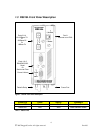
Figure 1 - RS910L Front Panel Description............................................................................................... 6
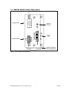
Figure 2 - RS910L Bottom Panel Description............................................................................................ 7
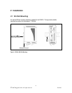
Figure 3 - RS910L DIN Rail Mounting....................................................................................................... 8
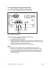
Figure 4 - RS910L Power Supply Inputs.................................................................................................... 9
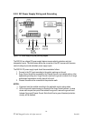
Figure 5 - DC Power supply wiring and grounding diagram................................................................. 10
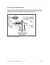
Figure 6 - Dielectric Strength Testing....................................................................................................... 11
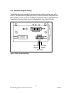
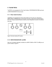
Figure 7 - RS910L Failsafe Output Relay ................................................................................................ 12
Figure 8 - RS232 Female DCE pin-out ..................................................................................................... 13
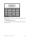
Figure 9: Fiber Serial Interface (ST Connector) ..................................................................................... 14
Figure 10: DB9 Port pin-out...................................................................................................................... 15
Figure 11: RJ45 Port pin-out..................................................................................................................... 16
Figure 12: Conceptual recommended RS485 wiring diagram ............................................................... 17
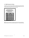
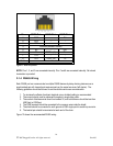
Figure 13 - RJ11 port pin-out and LEDs.................................................................................................. 18
Figure 14 - RJ45 Ethernet port pin-out.................................................................................................... 20
Figure 15: 10FL ST connector.................................................................................................................. 21
Figure 16: 100FX MTRJ connector......................................................................................................... 21
Figure 17: 100FX ST connector ............................................................................................................... 21
Figure 18: 100FX LC connector............................................................................................................... 22
Figure 19: 100FX SC connector ............................................................................................................... 22
Figure 20: Ethernet panel LED description............................................................................................ 22
Figure 21 - Mechanical Specifications ...................................................................................................... 26
Table of Tables
Table 1 - Status LEDs................................................................................................................................... 6
Table 2 - RJ11 port pin-out ....................................................................................................................... 18
Table 3 - RJ11 port LED description........................................................................................................ 18
Table 4 - Typical Performance on 24 AWG PIC twisted-pair................................................................ 19
Table 5 - RJ45 Ethernet port pin-out ....................................................................................................... 21
Table 6 - Operating Environment............................................................................................................. 23
Table 7 - Power Supply Specifications...................................................................................................... 23
Table 8 - Failsafe Relay Specifications...................................................................................................... 23
Table 9 – RJ1 Ethernet over VDSL Port Specifications ......................................................................... 24
Table 10: Copper Port Specification......................................................................................................... 24
Table 11: Fiber Optic Port Specification.................................................................................................. 24
Table 12: Ethernet Ports - Copper Specifications ................................................................................... 25
Table 13: Ethernet Ports – Fiber Optic Specifications........................................................................... 25
Table 14 - Communication Standard Compliance .................................................................................. 25
Table 15 - Mechanical Specifications........................................................................................................ 26
Table 16 - IEC 61850-3 Type Tests........................................................................................................... 27
Table 17 - IEEE 1613 Type Tests.............................................................................................................. 28
Table 18 - Environmental Type Tests....................................................................................................... 28