Product Overview
1.4.1 Fiber Optic Transceiver Orientation and Connection
Depending on the order code of the product, the RSG2300 can be equipped with
several different types of fiber optic ports. The Transmit (TX) and Receive (RX)
connections of each port must be properly connected and matched for proper link
and operation. Modules populated on the top row of the device typically have
locking mechanisms or tabs facing the top of the unit. Modules located on the
bottom row of the device have locking mechanisms or tabs facing the bottom of
the unit.
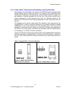
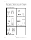
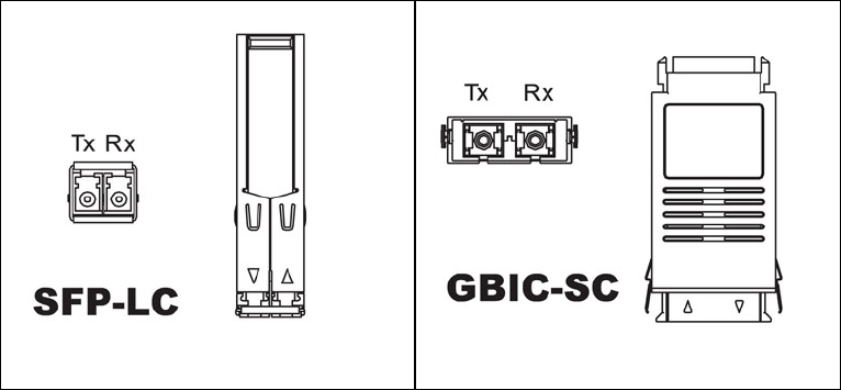
The diagrams in this section depict each fiber connector style supported by the
RuggedSwitch
®
in order to provide a reference for the proper orientation of cable
connections. A front view (looking into the connector) and a top view of the
connector module are shown for each one. Note that if modules are populated on
the bottom row of the device, the transceiver orientation will be inverted relative
to the diagram (i.e. RX and TX will be reversed).
Figure 5 and Figure 6 show front and top views of the pluggable fiber transceiver
modules supported by RuggedSwitch
®
. Note that when the module is installed in
the unit, most of the body of the module as shown in top views below will not be
visible.
Table 1: Pluggable Fiber Transceiver Modules
Figure 5: 1000LX SFP (mini-GBIC)
Module and LC connector
Figure 6: 1000LX GBIC connector
11
© 2008 RuggedCom Inc. All rights reserved Rev100


