


3. Installation
RuggedCom® RuggedBackbone™ 22 RX1501 Installation Guide Rev 104
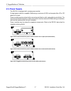
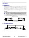
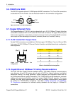
3.2. Power Supply Wiring and Grounding
The RX1501 supports a single power supply, power module 1 (PM1). Power connections are
located on the PM1 module face plate. An optional chassis ground connection is located on the
front panel as shown in Figure 2.2, “Front View - RX1501”.
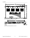
RX1501 products can be equipped with either a Phillips Screw Terminal Block or a Phoenix Plug
Terminal Block. The Phillips Screw Terminal Block has Phillips screws with compression plates,
allowing either bare wire connections or crimped terminal lugs. We recommend the use of #6 size
ring lugs to ensure secure, reliable connections under severe shock or vibration. Both terminal
blocks have a safety cover, secured with two Phillips screws, which must be removed to make
connections. The safety cover must be re-attached after wiring to ensure personnel safety.
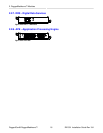
For AC and DC power supply wiring examples, refer to Section 3.2.4, “AC Power Supply Wiring
Example” and Section 3.2.5, “DC Power Supply Wiring Example ”.
The RX1501 has one (1) power supply installed. Service personnel must isolate all
power supplies prior to servicing.
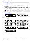
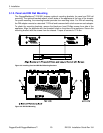
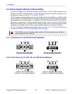
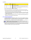
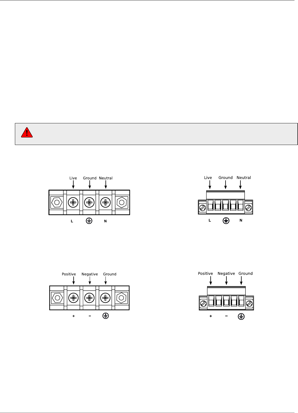
3.2.1. Connectors for HI and HIP Power Modules
Figure 3.8. Screw Terminal Power
Connector for HI Power Module
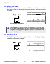
Figure 3.9. Pluggable Phoenix Power
Connector for HIP Power Module
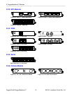
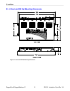
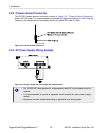
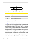
3.2.2. Connectors for 24, 24P, 48, and 48P Power Modules
Figure 3.10. Screw Terminal Power
Connector for 24 and 48 Power Modules
Figure 3.11. Pluggable Phoenix Power
Connector for 24P and 48P Power Modules