


3. Installation
RuggedCom® RuggedBackbone™ 28 RX1501 Installation Guide Rev 104
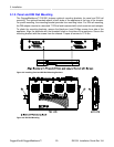
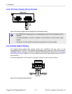
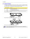
3.8. Serial Ports: RJ45
The RX1501 supports serial port line modules with RJ45 connections. On power-up, all serial
ports default to RS485 mode. Each port can be individually set to RS232, RS485, or RS422 mode
via software.
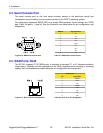
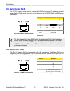
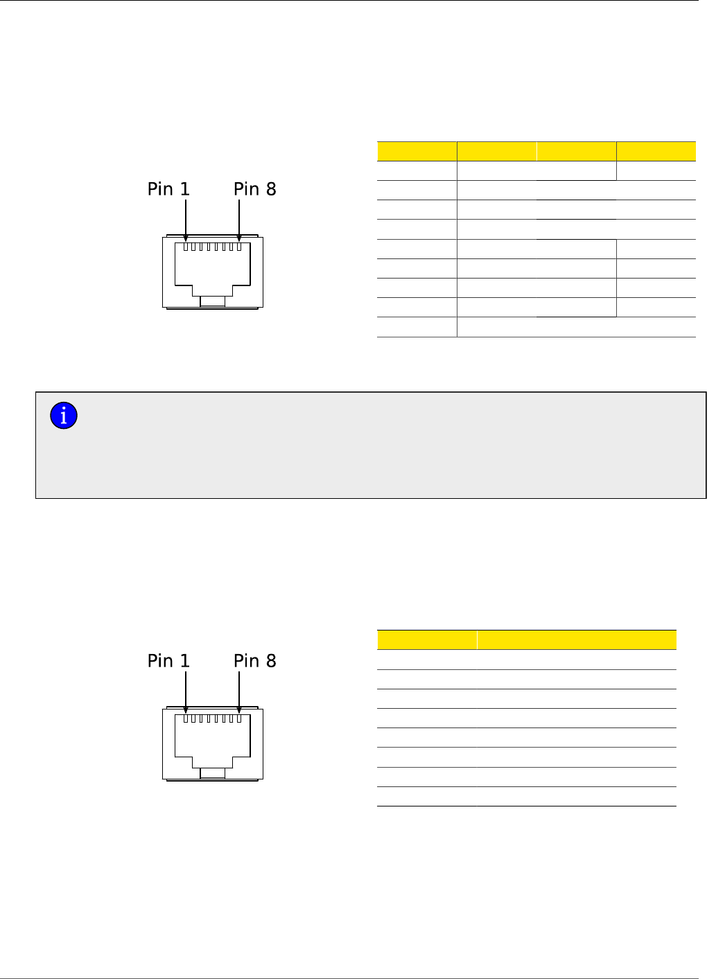
Figure 3.20. RJ45 Serial Pin Configuration
Pin RS232 Mode RS485 Mode RS422 Mode
1 RX-
2 Reserved
3 COM (Isolated GND)
4 COM (Isolated GND)
5 RX RX+
6 TX TX/RX + TX +
7 CTS
8 RTS TX/RX - TX -
Shield Chassis GND
Table 3.5. RJ45 RS232/RS485/RS422 Serial Pin
Assignment
Pin 2 is reserved for future IRIG-B output. Do not connect Pin 2 at this time; doing
so may cause hardware damage. Pins 7 and 8 are connected internally. No internal
termination is provided. In RS232 mode, these pins enter a high impedance state.
A DTE that asserts RTS will see CTS asserted, but hardware flow control is not
performed on the port.
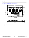
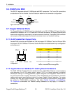
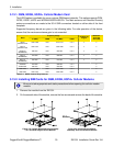
3.9. DDS Ports: RJ45
The RX1501 supports DDS port line modules with RJ45 connections. The 56 kbps DDS port is
compatible with Bellcore standards. Each DDS module features a single 56/64 kbps DDS line
interface with a standard RJ45 receptacle.
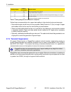
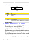
Figure 3.21. RJ45 DDS Pin Configuration
RJ45 Pin Description
1 R1: Transmit data to network (Ring 1)
2 T1: Transmit data to network (Tip 1)
3 NC
4 NC
5 NC
6 NC
7 T: Receive data from network (Tip)
8 R: Receive data from network (Ring)
Table 3.6. RJ45 DDS Pin Assignment