


RuggedBackbone™ RX1501
RuggedCom® RuggedBackbone™ 5 RX1501 Installation Guide Rev 104
List of Figures
2.1. RX1501 Chassis Slot Assignment .................................................................................... 12
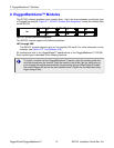
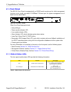
2.2. Front View - RX1501 ........................................................................................................ 13
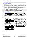
2.3. CG01: 2 × 10/100/1000TX RJ45 ...................................................................................... 14
2.4. 6TX01: 6 × 10/100/1000TX RJ45 ..................................................................................... 14
2.5. FX**/FG**: 2 × 100FX/1000SX/1000LX LC ...................................................................... 14
2.6. 4FX**: 4 × 100FC LC ....................................................................................................... 14
2.7. FX03: 2 × 100 FX MTRJ .................................................................................................. 14
2.8. 4FX03: 4 × 100FX MTRJ ................................................................................................. 14
2.9. FX**: 2 × 100FX SC ......................................................................................................... 14
2.10. FX**: 2 × 100FX ST ....................................................................................................... 14
2.11. 10FL: 3 × 10FL ST ......................................................................................................... 14
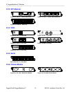
2.12. FG5*: 2 × 1000LX/1000SX SFP ..................................................................................... 15
2.13. FX5*: 4 × 100FX/100LX/100SX SFP .............................................................................. 15
2.14. 6FX50: 6 × 100FX SFP .................................................................................................. 15
2.15. TC1: 1 × T1/E1 RJ45 ..................................................................................................... 15
2.16. E01: 1 × E1 BNC ........................................................................................................... 15
2.17. TC2: 2 × T1/E1 RJ45 ..................................................................................................... 15
2.18. E02: 2 × E1 BNC ........................................................................................................... 15
2.19. TC4: 4 × T1/E1 RJ45 ..................................................................................................... 15
2.20. 6S01: 6 × Serial RJ45 .................................................................................................... 15
2.21. W11, W21, W32 Cellular Modem ................................................................................... 15
2.22. W12, W22 Cellular Modem ............................................................................................. 15
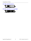
2.23. D02: 1 × DDS RJ45 ....................................................................................................... 16
2.24. APE 1402 ........................................................................................................................ 16
2.25. Screw terminal block power module: terminal cover in place (HI module shown) ........... 17
2.26. Screw terminal block power module: terminal cover removed (HI module shown) .......... 17
2.27. Pluggable terminal block power module (HIP module shown) ........................................ 17
3.1. Side View of Mounting Brackets ....................................................................................... 18
3.2. RX1501Rack Mounting Dimensions – Front View ............................................................ 18
3.3. RX1501Rack Mounting Dimensions – Top View .............................................................. 19
3.4. RX1501Rack Mounting Dimensions – Rear View ............................................................. 19
3.5. Installing Panel and DIN Rail Mounting Brackets ............................................................. 20
3.6. DIN Rail Mounting ............................................................................................................ 20
3.7. Panel and DIN Rail Mounting Dimensions ....................................................................... 21
3.8. Screw Terminal Power Connector for HI Power Module .................................................. 22
3.9. Pluggable Phoenix Power Connector for HIP Power Module ........................................... 22
3.10. Screw Terminal Power Connector for 24 and 48 Power Modules .................................. 22
3.11. Pluggable Phoenix Power Connector for 24P and 48P Power Modules ......................... 22
3.12. Chassis Ground Connection ........................................................................................... 23
3.13. Wiring for Single AC Power Supply (HIP module shown) ............................................... 23
3.14. Wiring for Single DC Power Supply (24P or 48P module shown) ................................... 24
3.15. Critical Alarm Relay Connector ....................................................................................... 24
3.16. DB9 Serial Console Port ................................................................................................. 25
3.17. RJ45 T1/E1 Pin Configuration ........................................................................................ 25
3.18. RJ45 T1/E1 Pin Configuration ........................................................................................ 26
3.19. RJ45 Ethernet Pin Configuration .................................................................................... 26