


3. Installation
RuggedCom® RuggedBackbone™ 30 RX1501 Installation Guide Rev 104
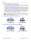
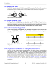
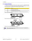
3.11.1. Module Insertion – SFP
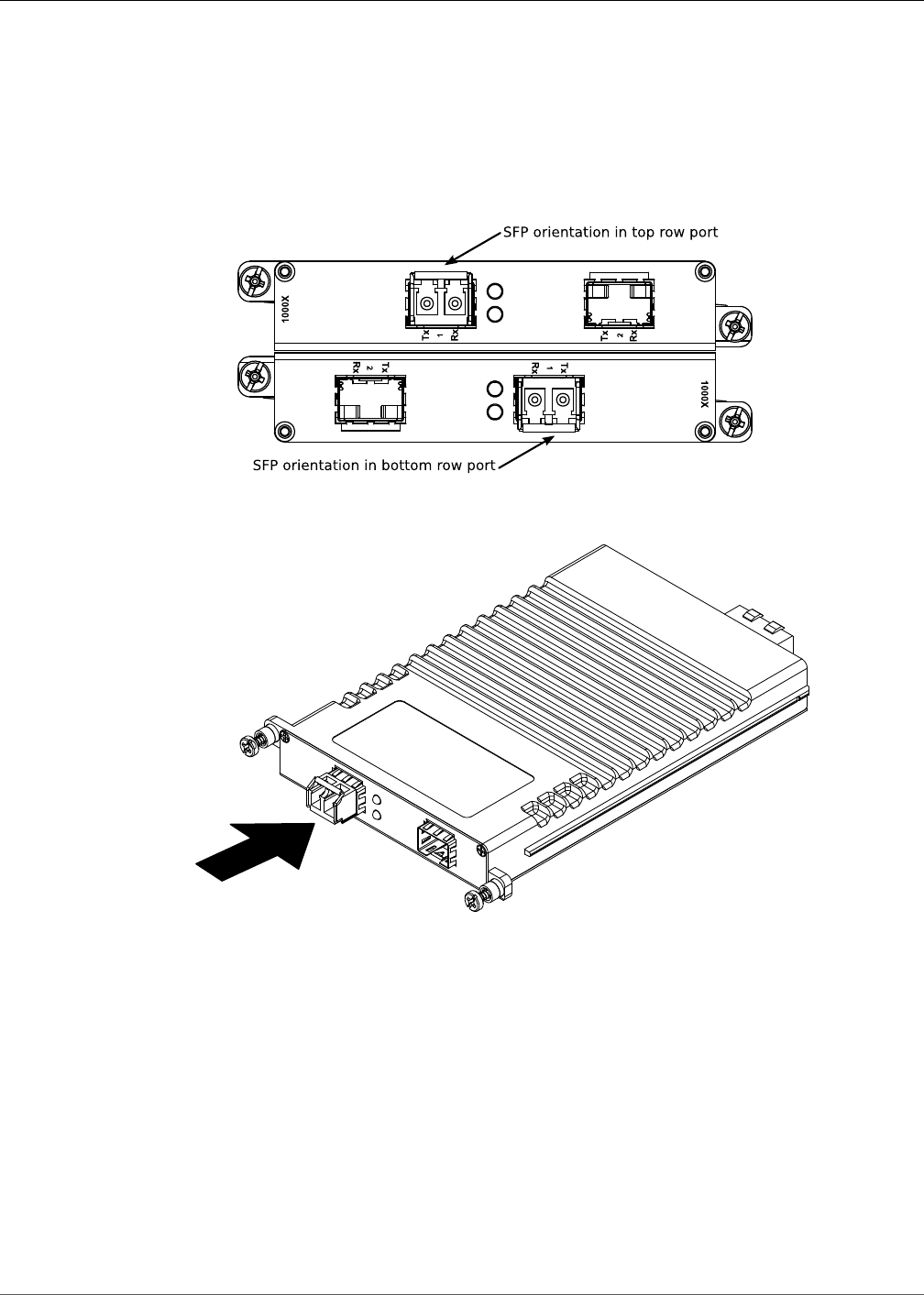
Special attention must be paid to the orientation of SFP modules upon installation in the RX1501
chassis. The figure below shows the proper orientation of SFP modules installed in both upper and
lower line modules. SFP modules on the upper row must be inserted top-side up. SFP modules
on the lower row must be inserted top-side down. SFP modules should be inserted with the bail-
latch in the locked position.
Figure 3.23. SFP module orientation
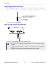
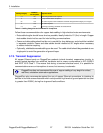
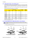
Figure 3.24. SFP module insertion
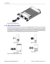
SFP modules should slide gently into their ports and should lock in place when fully inserted.
Dust covers should be in place when installing the modules, and should always be in place when
cables are not connected.
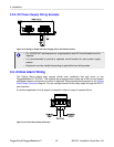
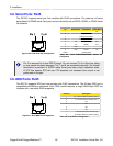
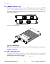
3.11.2. SFP Module Removal
To remove the SFP module, disconnect any cables and replace the dust cover to protect the
optics. Extend the bail latch found on the top of the module. Grasp the bail latch and gently pull
outwards to unlock and remove the module.
Immediately after removal, store the SFP module in an ESD-safe environment.