


3. Installation
RuggedCom® RuggedBackbone™ 24 RX1501 Installation Guide Rev 104
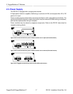
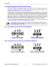
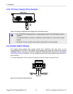
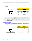
3.2.5. DC Power Supply Wiring Example
+
Figure 3.14. Wiring for Single DC Power Supply (24P or 48P module shown)
• For 125/230VAC rated equipment, a appropriately rated AC circuit breaker must be
installed.
• It is recommended to provide a separate circuit breaker for each power supply
module.
• Equipment must be installed according to applicable local wiring codes.
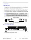
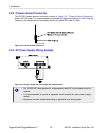
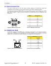
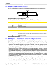
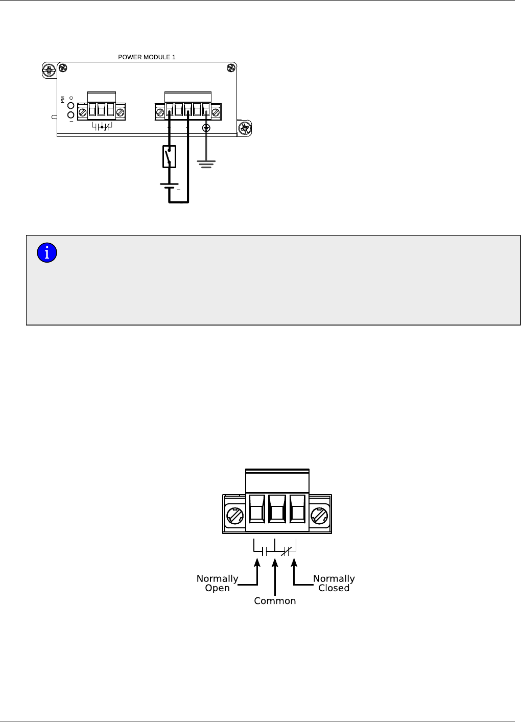
3.3. Critical Alarm Wiring
The Critical Alarm output relay signals critical error conditions that may occur on the
RuggedBackbone™ RX1501. The contacts are energized upon power-up of the unit and remain
energized unless a critical alarm condition is detected. Relay connections are shown in the Critical
Alarm Relay Connector diagram. You can configure control of the relay output through the ROX™
user interface.
A common application for this output is to signal an alarm in case of a power failure.
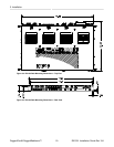
Figure 3.15. Critical Alarm Relay Connector