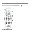
Controls and Functions
12 Runco VX-40d/-50d/-60d/-80d Owner’s Operating Manual
PRE
L
IMINAR
Y
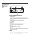
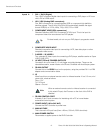
Inputs 3. DVI 1 / DVI 2 (Digital)
Two, HDCP-compliant digital video inputs for connecting a DVD player or HD tuner
with a DVI or HDMI output.
4. HD1 / HD2 (Analog BNC connectors)
Five, BNC connectors for connecting either RGB or component high-definition
television signals. The VX-40d/-50d/-60d/-80d automatically detects the signal
format: RGB(HV) or YPrPb, 480p, 720p, 480i, 576i or 1080i.
5. COMPONENT VIDEO (RCA connectors)
Standard Definition (480i/576i) Component (YPrPb) input. This is the input for
component video from sources such as DVD players.
6. COMPOSITE VIDEO INPUT
Standard composite video input for connecting a VCR, laser disc player or other
composite video source.
7. S-VIDEO 1 / S-VIDEO 2
Two, standard S-Video inputs for connecting a DVD player, satellite receiver or Super
VHS (S-VHS) VCR.
8. 12-VOLT (750 mA) TRIGGER OUTPUTS
Connection for up to three (3), 12-volt trigger-controlled devices. These can be
retractable screens, screen masks or the Runco CineWide with AutoScope system.
9. RS-232 OUTPUT
Connect this to the RS232 input on the projector, using the provided RJ11-to-DB9
adapter and communication cable.
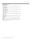
10. IR
Wired input from an external remote control or infrared receiver. It is a 3.5-mm, mini
phono jack, wired as follows:
Ring = +5V
Tip = IR Input
Sleeve = Ground
11. RS-232 CONTROL PORT
A female, 9-pin D-sub connector for interfacing with a PC or home theater
automation/control system.
12. POWER INPUT (100 to 240 VAC)
Connect the DHD Controller to power here.
13. MAIN AC FUSE
This is the main AC input fuse (5mm x 20mm, 500 mA, 250V slow-blow).
14. MAIN POWER SWITCH
Disconnects or applies power to the DHD Controller.
➤
For best results, do not run your DVD player in progressive mode.
When an external remote control or infrared receiver is connected
to the wired IR input, the IR sensor on the front of the DHD is
disabled.
Tip
Note


