18
Basic Setting and Operation
1. Complete peripheral connections before turning on the
transmitter.
2. Connect the AC power cord into an AC outlet. (see p.13) The
POWER indicator blinks red and then becomes red in stand-by
mode.
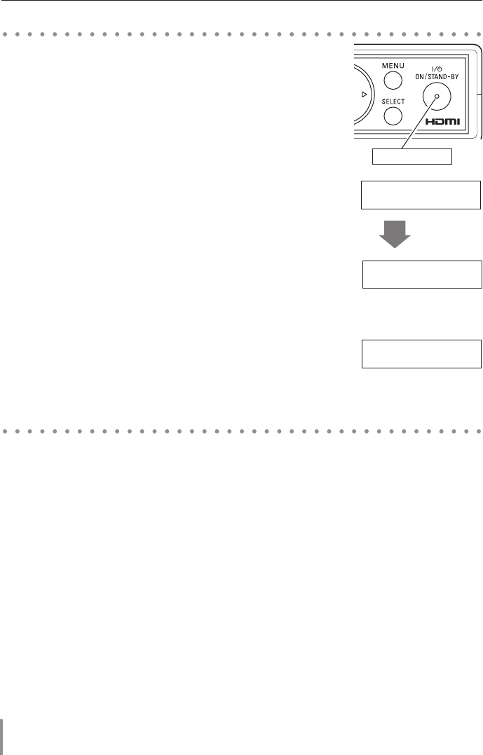
3. Press the ON/STAND-BY button. The POWER indicator
becomes green and the message "Hello HD Data Wireless"
appears on the LCD display for 4 seconds and then the input
source that was selected the last time appears on the LCD
display.
4. When the wireless communication is established with the
receiver, the LINK indicator lights up.
5. If the transmitter is locked with the Key Lock function, release
Lock Key. Refer to the Key Lock function on pages 32 - 33.
✐ If the Lock Key is not entered for 3 minutes after "Input Lock Key"
appeared, the transmitter will be turned off automatically.
1. Press the ON/STAND-BY button. The POWER indicator
becomes red and the display will disappear.
2. Unplug the AC power cord from the AC outlet.
Turning on the Transmitter
Turning off the transmitter
POWER indicator
INPUT SIGNAL >>
<none>
Link On
RF Freq. **.*MHz
Authentication
[Yes] NO
Authentication
Yes [NO]
Authenti- 1/2
cation
Transmission
[OK] NG
Phase 1/2
INPUT SIGNAL >>
[S] <none>
Input Lock Key
[#]### OK
Input Lock Key
#[#]## OK
Input Lock Key
##[#]# OK
INPUT SIGNAL >>
<none>
INPUT SIGNAL >>
<none>
INPUT SIGNAL >>
<none>
INPUT SIGNAL >>
<none>
INPUT SIGNAL >>
<none>
Wireless 2/5
Setup
Wireless 3/5
Initial Setup
Information 4/5
Key Lock 5/5
Key Lock 5/5
Video 1/5
Setup
Hello
HD Data Wireless
INPUT SIGNAL >>
<none>
INPUT SIGNAL >>
<none>
INPUT SIGNAL >>
<none>
INPUT SIGNAL >>
<none>
INPUT SIGNAL >>
<none>
H Freq.
V Freq.
H Rez. ****
V Rez. ****
Initialize 2/2 Initialize
[YES] NO
Initialize
YES [NO]
Transmission
OK [NG]
H Position 2/2
INPUT SIGNAL >>
[S] XGA 1
Input Lock Key
###[#] OK
Input Lock Key
#### [OK]
INPUT SIGNAL >>
[B] XGA 1
INPUT SIGNAL >>
<none>
INPUT SIGNAL >>
<none>
INPUT SIGNAL >>
<none>
INPUT SIGNAL >>
<none>
INPUT SIGNAL >>
<none>
Link On
RF Freq. **.*MHz
Authentication
[Yes] NO
Authentication
Yes [NO]
Authenti- 1/2
cation
Transmission
[OK] NG
Phase 1/2
INPUT SIGNAL >>
[S] <none>
Input Lock Key
[#]### OK
Input Lock Key
#[#]## OK
Input Lock Key
##[#]# OK
INPUT SIGNAL >>
<none>
INPUT SIGNAL >>
<none>
INPUT SIGNAL >>
<none>
INPUT SIGNAL >>
<none>
INPUT SIGNAL >>
<none>
Wireless 2/5
Setup
Wireless 3/5
Initial Setup
Information 4/5
Key Lock 5/5
Key Lock 5/5
Video 1/5
Setup
Hello
HD Data Wireless
INPUT SIGNAL >>
<none>
INPUT SIGNAL >>
<none>
INPUT SIGNAL >>
<none>
INPUT SIGNAL >>
<none>
INPUT SIGNAL >>
<none>
H Freq.
V Freq.
H Rez. ****
V Rez. ****
Initialize 2/2 Initialize
[YES] NO
Initialize
YES [NO]
Transmission
OK [NG]
H Position 2/2
INPUT SIGNAL >>
[S] XGA 1
Input Lock Key
###[#] OK
Input Lock Key
#### [OK]
INPUT SIGNAL >>
[B] XGA 1
INPUT SIGNAL >>
<none>
INPUT SIGNAL >>
<none>
INPUT SIGNAL >>
<none>
INPUT SIGNAL >>
<none>
after 4 seconds
INPUT SIGNAL >>
<none>
Link On
RF Freq. **.*MHz
Authentication
[Yes] NO
Authentication
Yes [NO]
Authenti- 1/2
cation
Transmission
[OK] NG
Phase 1/2
INPUT SIGNAL >>
[S] <none>
Input Lock Key
[#]### OK
Input Lock Key
#[#]## OK
Input Lock Key
##[#]# OK
INPUT SIGNAL >>
<none>
INPUT SIGNAL >>
<none>
INPUT SIGNAL >>
<none>
INPUT SIGNAL >>
<none>
INPUT SIGNAL >>
<none>
Wireless 2/5
Setup
Wireless 3/5
Initial Setup
Information 4/5
Key Lock 5/5
Key Lock 5/5
Video 1/5
Setup
Hello
HD Data Wireless
INPUT SIGNAL >>
<none>
INPUT SIGNAL >>
<none>
INPUT SIGNAL >>
<none>
INPUT SIGNAL >>
<none>
INPUT SIGNAL >>
<none>
H Freq.
V Freq.
H Rez. ****
V Rez. ****
Initialize 2/2 Initialize
[YES] NO
Initialize
YES [NO]
Transmission
OK [NG]
H Position 2/2
INPUT SIGNAL >>
[S] XGA 1
Input Lock Key
###[#] OK
Input Lock Key
#### [OK]
INPUT SIGNAL >>
[B] XGA 1
INPUT SIGNAL >>
<none>
INPUT SIGNAL >>
<none>
INPUT SIGNAL >>
<none>
INPUT SIGNAL >>
<none>


