Unit 3: Installation
SATO GT4xxe Series Operator Manual PN 9001138A Page 3-13
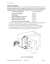
INTERFACE UPGRADE
The printer is typically ordered with a high-speed parallel interface board installed. However,
interface requirements sometimes change and an upgrade is desired. All of the interface boards
are installed within the same slot (middle) located in the rear of the printer with little or no
difference in installation methodology with the exception of the mini-LAN interface (top slot).
Parallel Interface (IEEE1284) (Optional or Bundled)
Serial Interface (RS232C) (Optional)
USB Interface (Optional)
10BaseT/100Base-TX Lan Interface (Optional)
Wireless LAn 802.11b Interface (Optioanl)
10BaseT/100Base-TX mini LAN (Optional(
EXT Connector (External Signal Interface) (Optional)
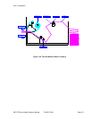
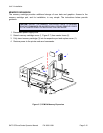
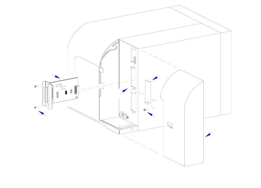
1 Remove the rear housing cover (1, Figure 3-8). Disconnect the power and interface cords.
2 Remove screw (2) and plate (3) as required to expose the interface port.
3 Remove two screws (4) and withdraw existing board (5) from frame (6) as required.
4 Insert replacement board (5) into slot in frame (6) and secure using two screws (4).
5 Connect the interface cord, power cord, and reinstall rear housing covers.
Figure 3-8, Interface Upgrade
1
I
E
E
E
1
2
8
4
+
R
S
B
O
A
R
D
2
I
E
E
E
1
2
8
4
+
R
S
B
O
A
R
D
3
4
5
6


