


16 SBC-350A User's Manual
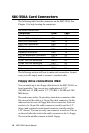
SBC-350A Card Connectors
The following table lists the connectors on the SBC-350A. See
Chapter 1 for help locating the connectors.
SBC-350A Connectors
Component Label Page
Reset switch connector J1 19
Power LED and Keylock CN1 19
HDD LED connector CN2 19
HDD (IDE) connector CN3 17
FDD connector CN4 16
Parallel port CN5 18
Keyboard connector CN6 18
PC/104 expansion connector CN7/8 43
SBC power connector CN9 20
COM1 RS-232 serial port CN10 20
COM2 RS-232 serial port CN11 20
Keyboard connector (6-pin mini DIN)CN12 18
External speaker connector CN13 21
The following sections tell how to make each connection. In most
cases you will simply need to connect a standard cable.
Floppy drive connections (CN4)
You can attach up to two floppy disk drives to the SBC-350A's on-
board controller. You can use any combination of 5.25"
(360 KB and 1.2 MB) and/or 3.5" (720 KB, 1.44 MB and 2.88
MB) drives.
The card comes with a 34-pin daisy-chain drive connector cable.
On one end of the cable is a 34-pin flat-cable connector. On the
other end are two sets of floppy disk drive connectors. Each set
consists of a 34-pin flat-cable connector (usually used for 3.5"
drives) and a printed-circuit-board connector (usually used for
5.25" drives). You can use only one connector in each set. The set
on the end (after the twist in the cable) connects to the A: floppy.
The set in the middle connects to the B: floppy.