


Chapter 3 Connecting peripherals 17
Attach the single 34-pin flat-cable connector to CN4 on the CPU
card. For help finding the connector, see Chapter 1. Wire number 1
on the cable is red or blue, the other wires are gray. Make sure that
the red wire corresponds to pin one on the connector (on the right
side).
Connect the A: floppy drive to the connector set on the other end
of the cable. If you are connecting a 5.25" floppy drive, line up the
slot in the printed-circuit-board (golden fingers) with the blocked-
off part of the cable connector.
If you are connecting a 3.5" floppy drive, you may have trouble
determining which pin is number one. Look for a number printed
on the circuit board indicating pin number one. Also, the connector
on the floppy drive connector may have a slot. When the slot is up,
pin number one should be on the right. Check the documentation
that came with the drive for more information.
Next, if you desire, connect the B: floppy drive to the connectors in
the middle of the cable as described above.
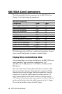
IDE hard drive connections (CN3)
You can attach two IDE (Integrated Device Electronics) hard disk
drives to the SBC-350A internal controller. The card comes with a
40-pin flat-cable piggyback cable. This cable has three identical
40-pin flat-cable connectors.
Wire number 1 on the cable is red or blue, the other wires are gray.
Connect one end to connector CN3 on the CPU card. Make sure
that the red wire corresponds to pin one on the connector (on the
right side). See Chapter 1 for help finding the connector.
Unlike floppy drives, IDE hard drives can connect in either
position on the cable. If you install two drives, you will need to set
one as the master and one as the slave. You do this using jumpers
on the drives. If you use just one drive, you should set it as the
master. See the documentation that came with your drive for more
information.