63230-216-207/A3 Chapter 4—Connections
9/2002 RS-485 Ports
13
© 2002 Schneider Electric All Rights Reserved
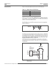
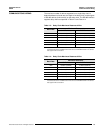
RS-485 PORTS Table 4–2 shows the default values for each of the RS-485 ports.
NOTE: On a 4-wire mixed mode (POWERLOGIC and Modbus) daisychain,
device address 1 cannot be a POWERLOGIC or SY/MAX device and device
address 16 cannot be a Modbus device.
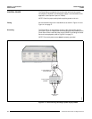
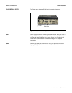
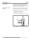
Each RS-485 port is a male DB-9 connector with the pin-out arrangement
shown in Figure 4–5.
Figure 4–5: Male DB-9 connector (master port)
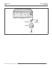
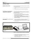
Two DB9-to-terminal block adapters (female) [Square D part no. DB9F2TB]
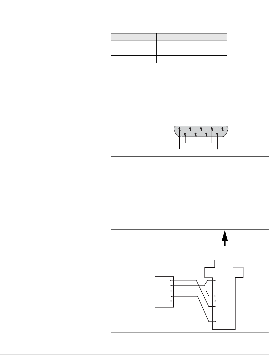
are included with the Power Server. To connect the daisy chain of devices to
the RS-485 port, attach an adapter to a Belden 8723 or equivalent cable and
plug the adapter into the COM 3 or COM 4 port on the Power Server. Wire
the cable and adapter as shown in Figure 4–6.
NOTE: Because of pin out configurations, it is necessary to make these
connections as described. Square D cable CAB-107 is not compatible with
this application.
Figure 4–6: Typical POWERLOGIC standard device connection to
Power Server
Table 4–2: Default Values for RS-485 Ports
Value Default Setting COM 3 and COM 4
Type 4-wire
Baud Rate Speed 19200
Parity Even
Male DB-9 of
Power Server
1
2345
67 8
9
SHIELD
Rx–
Rx+
Tx–
Tx+
Rx +
Green
White
Red
Black
Rx –
Tx +
Tx –
Shield
(IN+)
(IN–)
(OUT+)
(OUT–)
(Shld)
1 Tx –
2
3
4 Rx +
5 Shield
6 Tx +
7
8
9 Rx –
4-Wire
typical standard
POWERLOGIC
slave device
DB9F2TB to
Power Server
30703009


