Chapter 1—Introduction 63230-216-207/A3
Overview 9/2002
© 2002 Schneider Electric All Rights Reserved
2
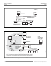
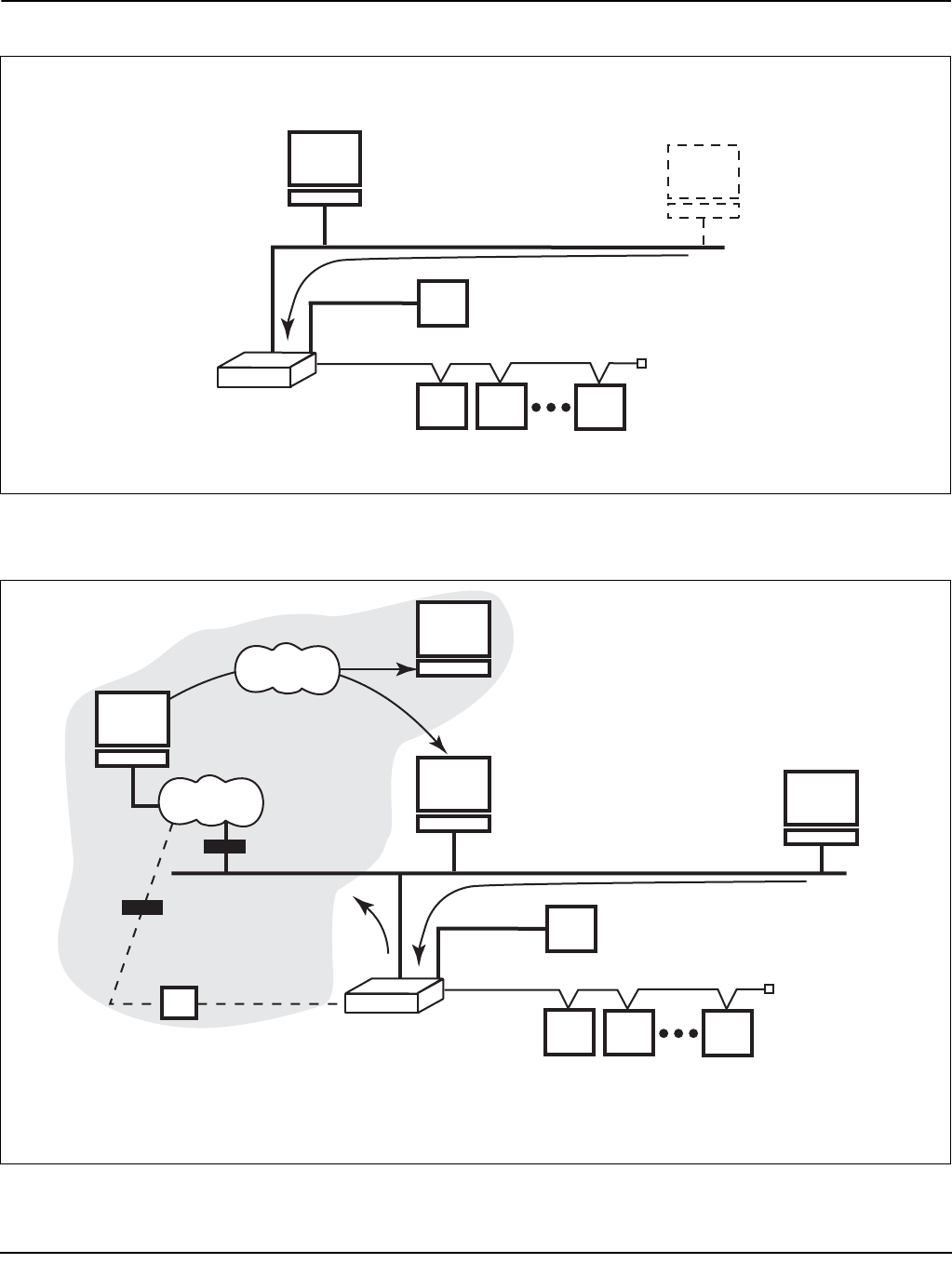
Figure 1–2: The Power Server used as a standalone system monitoring device
Figure 1–3: The Power Server used as a gateway device with SMS and a web server
Initial setup
via
NetMeeting
Power Server used as a
component of the
POWERLOGIC System
Mixed-mode daisy chain
Device setup for the
POWERLOGIC System
Web browser
Optional
touch screen
30703059
PC with
System Manager
Software (SMS)
Power Server used as
a gateway
Mixed-mode daisy chain
PUSH application
sending data to
enterprise
via Ethernet
via
Modem
Internet
Internet
POWERLOGIC Enterprise System
30703054
POWERLOGIC
Enterprise System
View reports via
Internet browser
Firewall
Firewall
NOTE: The shaded area depicts a POWERLOGIC Enterprise System. Contact
POWERLOGIC Engineering Services for information on this type of application.
Optional
touch screen
Web browser


