


26 Barracuda 4 Installation Guide, Rev. E
Mounting the drive and connecting cables
Note. This mounting procedure does not apply to WC or
DC model drives. To mount a WC or DC drive,
plug the drive into the system's single connector
attachment (SCA) position on the system's back
panel.
Do not touch the connector pins or any components on
the control board without observing static-discharge
precautions. Always handle the drive by the frame only.
The drive may be mounted in any orientation (horizon-
tally, vertically, and any combination thereof); however,
you must ensure that the drive receives adequate air
flow for cooling.
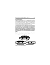
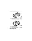
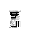
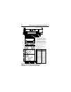
1. Mount the drive to the host system’s chassis using
four 6-32 UNC screws. Two mounting holes are in
each side of the drive and there are four mounting
holes in the bottom of the drive. See Figures 6, 7 or 8.
The maximum length that the screws should ex-
tend into the chassis mounting holes is 0.15 inch
(3.81 mm), measured from the outer surface of the
chassis. Tighten the screws down evenly. Do not
over-tighten or force the screw if it does not seem to
screw in easily, because this means the threads are
not properly aligned. In this case, back the screw out
and try again.