35
E
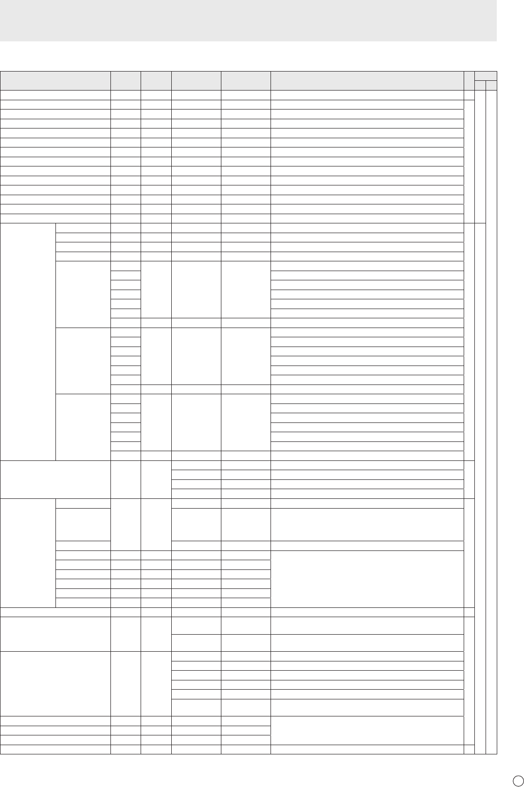
PICTURE menu
Function
Command Direction
Parameter Reply Control/Response contents *1
*2
(A) (B)
AUTO AGIN W 1 When the input mode is PC D-SUB, PC RGB. -
○
○
ANALOG GAIN ANGA WR 0-127 0-127 When the input mode is PC D-SUB, PC RGB.
○
ANALOG OFFSET ANOF WR 0-127 0-127 When the input mode is PC D-SUB, PC RGB.
CONTRAST CONT WR 0-60 0-60
BLACK LEVEL BLVL WR 0-60 0-60
TINT TINT WR 0-60 0-60
COLORS COLR WR 0-60 0-60
SHARPNESS SHRP WR 0-24 0-24
RGB INPUT RANGE (AV HDMI) AHDR WR 0-2 0-2 0: AUTO, 1: FULL, 2: LIMITED
RGB INPUT RANGE (PC HDMI) PHDR WR 0-2 0-2 0: AUTO, 1: FULL, 2: LIMITED
RGB INPUT RANGE (AV DVI) ADVR WR 1-2 1-2 1: FULL, 2: LIMITED
RGB INPUT RANGE (PC DVI) PDVR WR 1-2 1-2 1: FULL, 2: LIMITED
RGB INPUT RANGE (D-SUB) PDSR WR 1-2 1-2 1: FULL, 2: LIMITED
RGB INPUT RANGE (PC BNC) PBRR WR 1-2 1-2 1: FULL, 2: LIMITED
ADVANCED
(When the input
mode is AV.)
FLESH TONE FLES WR 0-2 0-2 0: OFF, 1: LOW, 2: HIGH
○
○
3D-NR TDNR WR 0-2 0-2 0: OFF, 1: LOW, 2: HIGH
MPEG-NR MPNR WR 0-1 0-1 0: OFF, 1: ON
3D-Y/C YCSP WR 0-1 0-1 0: OFF, 1: ON (When the input mode is AV VIDEO)
C.M.S.-HUE CMHR WR -10-10 -10-10 R
CMHY Y
CMHG G
CMHC C
CMHB B
CMHM M
CRST W 1 Resets the hue.
C.M.S.-
SATURATION
CMSR WR -10-10 -10-10 R
CMSY Y
CMSG G
CMSC C
CMSB B
CMSM M
CRST W 2 Resets the saturation.
C.M.S.-VALUE CMVR WR -10-10 -10-10 R
CMVY Y
CMVG G
CMVC C
CMVB B
CMVM M
CRST W 3 Resets the brightness.
COLOR MODE BMOD WR 0 0 STD
○
2 2 VIVID
3 3 sRGB (When the input mode is PC)
4 4 HIGH ILLUMINANCE
WHITE BALANCE THRU CTMP WR 0 0 When the input mode is PC DVI-D/PC HDMI.
○
PRESET 1-18 1-18 From 1: approximately 3,000K to 15: approximately 10,000K
(500K steps)
16: approximately 5,600K, 17: approximately 9,300K,
18: approximately 3,200K
USER 99 99
R-CONTRAST CRTR WR 0-256 0-256 “ERR” when CTMP is not set to 99.
G-CONTRAST CRTG WR 0-256 0-256
B-CONTRAST CRTB WR 0-256 0-256
R-OFFSET OFSR WR -127-127 -127-127
G-OFFSET OFSG WR -127-127 -127-127
B-OFFSET OFSB WR -127-127 -127-127
COPY TO USER CPTU W 0 Copies a preset value to the user setting. -
GAMMA GAMM WR 0-2 0-2 0: 1.8, 1: 2.2, 2: 2.4 (during PC input)
0: LIGHT 2, 2: DARK (during AV input)
○
4-6 4-6 4: USER, 5: 2.0, 6: STD (during PC input)
4: USER, 5: LIGHT 1, 6: STD (during AV input)
DISPLAY COLOR PATTERN PTDF WR 0 0 No pattern display.
1 1 White single color pattern display.
2 2 Red single color pattern display.
3 3 Green single color pattern display.
4 4 Blue single color pattern display.
99 99 Red/green/blue mixed color pattern display.
Set each color's level with RED, GREEN, BLUE.
RED PTDR WR 0-15 0-15 “ERR” when PTDF is not set to 99.
GREEN PTDG WR 0-15 0-15
BLUE PTDB WR 0-15 0-15
RESET ARST W 2
-
Controlling the Monitor with a PC (RS-232C)


